


Hardware components | ||||||
 |
| × | 1 | |||
| × | 2 | ||||
| × | 1 | ||||
 |
| × | 1 | |||
Software apps and online services | ||||||
 |
| |||||
Think about a setup where you want to attach more than one SLF3x sensor to your development board. In the provided example, we show how you can attach multiple sensors on the same I²C bus, change their I²C addresses and thereafter read out measurements from the sensors.
The example here is built on the Arduino Platform with an ESP32 DevKit C Board. If you want to do the same on a RaspberryPi, there is an example in the Sensirion Raspberry Pi SF06-LF Driver Repository linked in the Code section at the end.
Limitations- After a soft or hard reset, the I²C address is set back to the default address 0x08. A soft reset is triggered by a special I²C command, see
i2c_soft_reset()in the example, and a hard reset is triggered by a power cycle of the sensor. - The feature is only supported by SLF3x sensors with a serial number above 23xxxxxxxx.
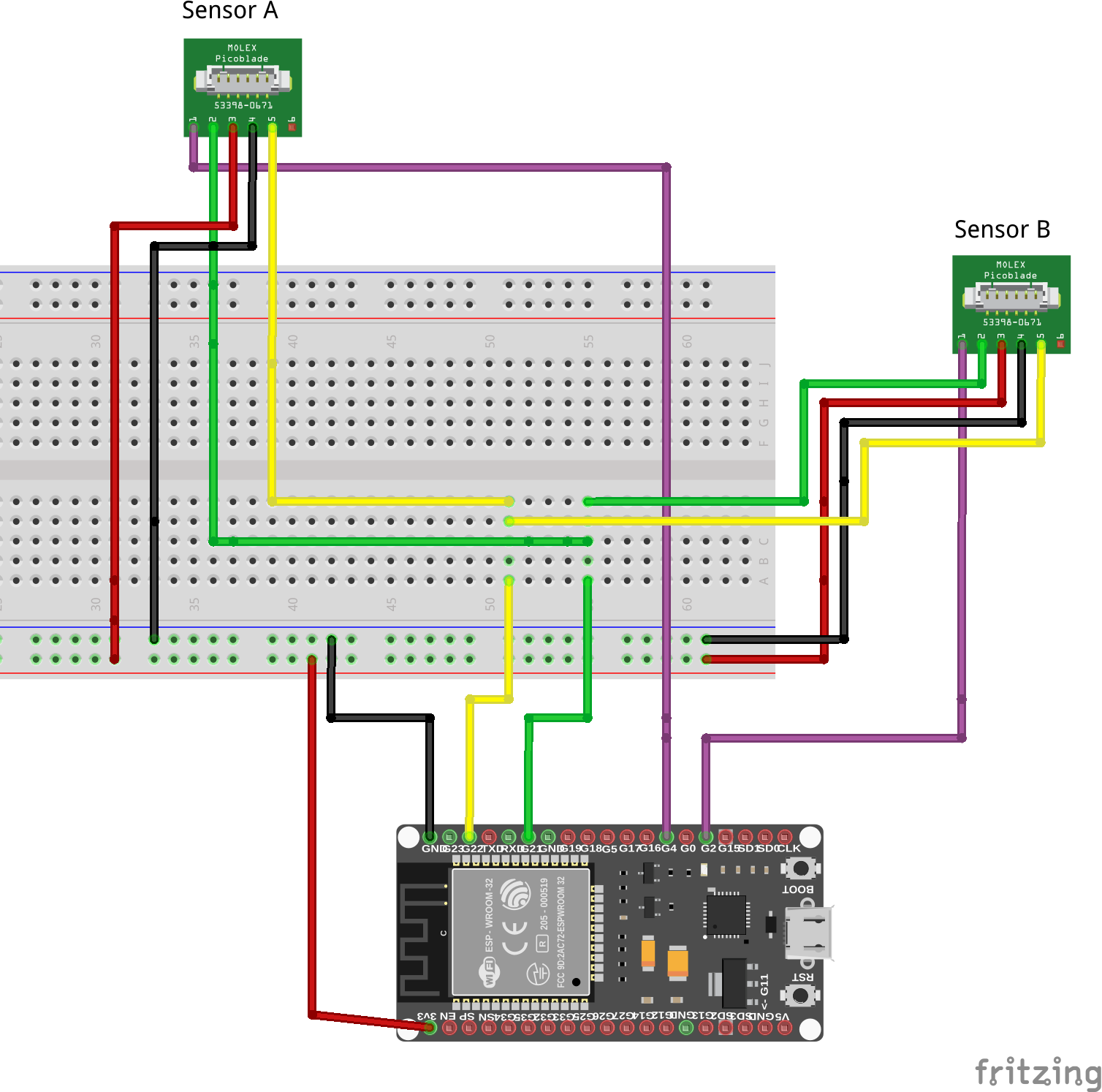
To connect the sensors it is best to attach pin headers to the Molex PicoBlade 6 pin cables. To make the wiring easy, use the following colors:
- Pin1 (IRQn) purple
- Pin2 (SDA) green
- Pin3 (VDD) red
- Pin4 (GND) black
- Pin5 (SCL) yellow
- Pin6 (unused) -
Be careful to get the wiring correct. Please note, that using the wrong wiring could damage your sensor!
Once you have the cables ready, take your breadboard and connect GND, VDD, SCL and SCD from the ESP board to the breadboard.
Next, connect GND, VDD, SCL, SCD from the breadboard to the two sensors.
Last, connect IRQn pin (pin 1) from one sensor to the GPIO pin 2 on the ESP board, and the IRQn pin (pin 1) from the second sensor to the GPIO pin 4 on the ESP board. Refer to the attached schematic if needed.
Code & Software SetupOpen the Arduino IDE, go to the Library Manager and install the Sensirion I2C SF06-LF library. Then go to "Examples" and choose i2cAddressChangeExample from Sensirion I2C SF06-LF.
Check that the defines for the IRQn pins match with wiring, for the wiring explained above it should be:
#define IRQN_PIN_SENSOR_A 4
#define IRQN_PIN_SENSOR_B 2
You can change the I²C address to use by changing the following lines. You can use any valid I²C address in the range of 0x0 to 0x7F.
#define I2C_ADDR_SENSOR_A 0x0A
#define I2C_ADDR_SENSOR_B 0x0B
Compile and run the example. Open a Serial Monitor and set the Baudrate to 115200. Press the reset button of your ESP32 to see the log output for the address change followed by sensor measurements, as you can see in the Screenshot below.
Note that you have to create two instances of the SensirionI2cSf06Lf class, one for each sensor. You pass the I²C address to the begin() method as you see in the following lines of code:
SensirionI2cSf06Lf sensorA;
SensirionI2cSf06Lf sensorB;
...

void setup() {
    ...
    sensorA.begin(Wire, 0x0A);
    sensorB.begin(Wire, 0x0B);
    ...
}This section details the steps used by the changeSensorAddress function in the above mentioned example.
The steps below should be performed for each sensor you wish to change the I²C address.
Note that you should not send any other commands to your sensor prior to performing the I²C address change sequence. The best is to perform a soft reset (special I²C command) or hard reset (power cycle) before starting to change the I²C addresses.
Be aware that once you changed the address, the sensor should not be reset as this would revert the I²C address change.
Perform a soft reset for all sensors attached to the I²C bus. Do this only once.
Wire.beginTransmission(0x00);
size_t writtenBytes = Wire.write(0x06);
uint8_t i2c_error = Wire.endTransmission();
Send the I²C address change command to the default sensor address 0x08. This command is received by all SLF3x sensors on the bus still having the default address.
SensirionI2CTxFrame txFrame =
SensirionI2CTxFrame::createWithUInt16Command(0x3661, buffer_ptr, 5);
txFrame.addUInt16(newI2cAddress);
localError = SensirionI2CCommunication::sendFrame(SLF3C_1300F_I2C_ADDR_08,
                                                  txFrame,
                                                  wire);
Select the sensor which should accept the new I²C address sent in step 1 by sending a high pulse of at least 150μs to its IRQn pin.
To do so, set the GPIO pin connected to the sensor's IRQn to output mode and set it to a high state for at least 150μs.
The sensor waits for such a pulse on the IRQn pin for 1.5ms after the I²C address change command has been sent.
pinMode(sensorIrqPin, OUTPUT);
digitalWrite(sensorIrqPin, HIGH);
delayMicroseconds(500);
digitalWrite(sensorIrqPin, LOW);
Change the GPIO pin back to low state and switch it to INPUT mode. You might want to configure it with a pull-down to avoid unintended high state.
pinMode(sensorIrqPin, INPUT_PULLDOWN);Wait 1.5ms after sending the I²C address change command.
Then, read out the GPIO IRQn pin, which should be set to high state for 200μs if the sensor changed its I²C address successfully.
We check for the high pulse in a loop to make sure we catch it.
delayMicroseconds(500);
uint8_t success = 0;
uint16_t cnt = 0;
while (success == 0 && cnt < 100) {
    cnt++;
    success = digitalRead(sensorIrqPin);
    delayMicroseconds(10);
}
For more details please refer to the documentation SLF3x-I2C-Address-change.


Comments
Please log in or sign up to comment.