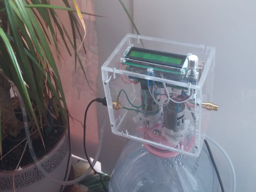
There are many familiar projects and tutorials in the Internet describing how to use the soil moisture sensors. In this project some brilliant ideas found in the Internet are combined together and accomplished with the software part to build the home plant watering system controller. Sometimes the solution is looking obvious till you come a little close to see the devil in the details. So let's investigate these details.
Main Features of the ControllerThis controller has the following features:
- Two plants is supported, the controller has two independent channels; any channel can be disabled
- Each channel has two general parameters: how long to pump the water forward and backward. These parameters are measured in tens of the second.
- The controller has manual mode. It is possible to water the plant by pushing the button.
- The controller checks the humidity after watering the plant. It disables the channel in case the humidity would not increased.
- The controller implements the light sensor to prevent running at night
- The controller has menu system to setup configuration parameters. Configuration is saved in the EEPROM.
How to measure the soil moisture accurately? You can order the sensor on eBay, put it in the plant and check the resistance. This way is described in many tutorials in the Internet. Unfortunately, in my case the resistance of "dry" and "wet" plant were so close (300 kOhm and 500 kOhm) it is hardly to decide accurately when we should add some water to our plant. The problem is that the clean water does not conduct the electricity, actually the minerals in the water does. So, the measured resistance hugely depends on amount and the type of minerals in the our plant, not on amount of water we applied to it. Google can help. In the Internet I have found brilliant idea to measure capacitance of the sensor, not resistance. The main idea is that the water have big dielectric permittivity and the capacitance of "wet" plant is much bigger than the "dry" one (200 mkF vs 200 pF) a million times difference!
How to Measure the Capacitance?Another genius people have turn the arduino to high accurate capacitor meter. But in my opinion this method is complicated and it is not necessary to measure the capacitance of our sensor so accurate. Another way to measure the capacitance is much more simpler, and uses only two analog pins and gives the acceptable accuracy to distinguish between "dry" and "wet" conditions of our plant. As i mention above, the readings of the "dry" and "wet" plant have a big difference, it is not convenient to use this value to set up a limit, so the natural logarithm of capacitance readings from the sensor is used in the code, to decrease the interval of possible values.
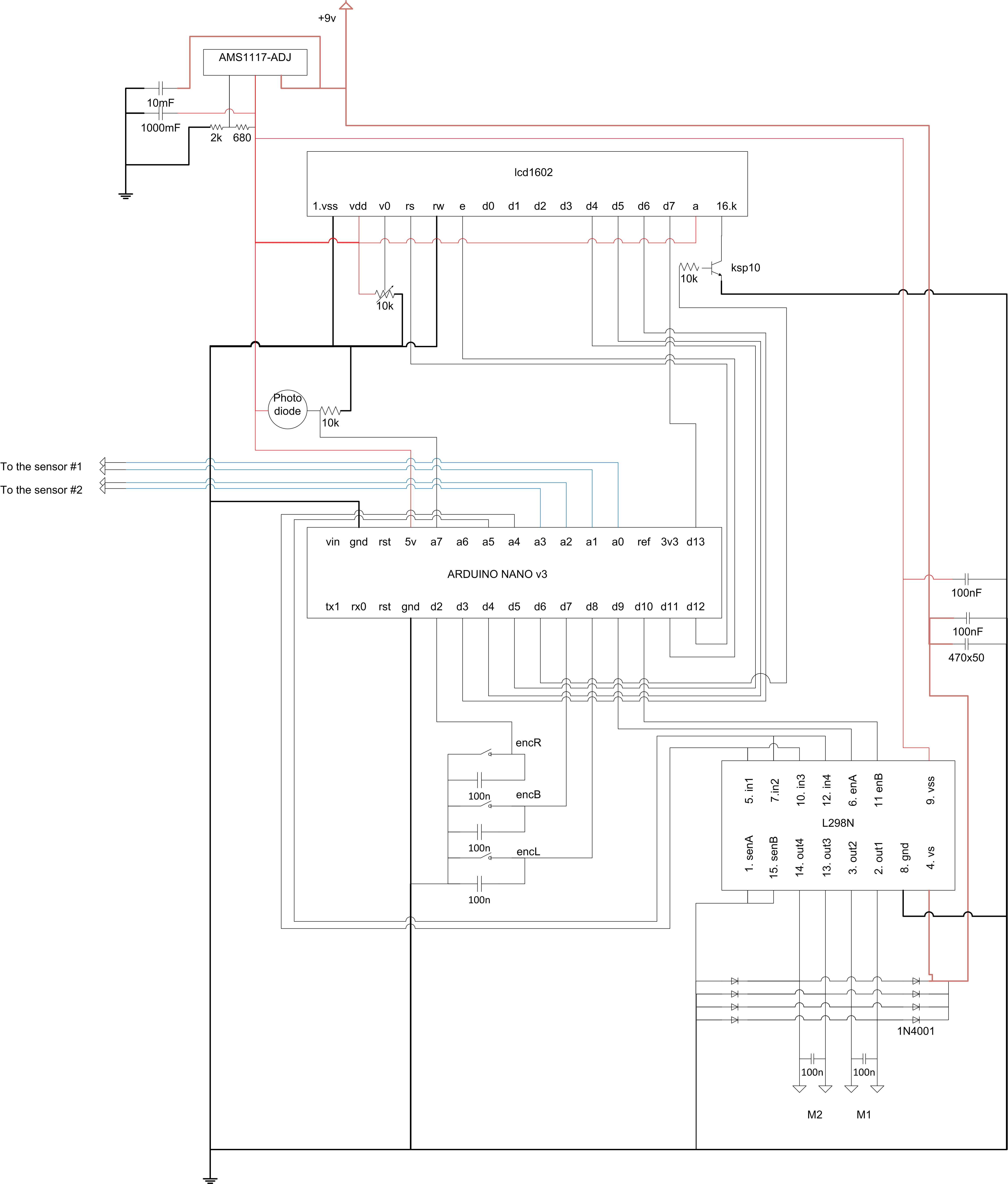
Why H-bridge?It seemed to be a good idea to use the single MOSFET transistor to run water pump. Unfortunately, the water level in the water source tank (bottle) can be higher than the our plant. In such a case, we start to pump the water, but it keep going after the pump is stopped. How to stop the water for sure? You can run the pump in the reverse direction for a while. Because we use the DC motor it is sufficient to revert the poles ("+" and "-"). To do so, you need to use the H-bridge. The L298n IC is good choice. The pumps in this project uses 9 V and 3 A, so you do need the heat sink on the IC and power resistor also. The power resistor of 1 Ohm 5Watt is used in this controller. The motor H-bridge L298n is suitable to manage two motors, so this controller can manage two plants simultaneously.
The Controller Menu SystemTo manage the plant controller the rotary encoder is used. After the controller starts, the main screen appears. On the main screen some useful parameters are displayed. The current sensor readings of both channels of the controller (in the upper line). If the channel is disabled, string "xxxx" displayed. On the bottom line the dry limits are displayed.
To manually run the pump, press the rotary encored shortly. The manual screen appears. To setup the controller parameters, press the encoder for long time (about 1 second) while in the main screen. The the setup menu three is described here:
- Left channel
- Right channel
- Display backlight brightness (or auto)
- Display backlight brightness at night
Each channel has own menu:
- channel enable
- dry limit
- pump forward running time (tens of second)
- pump backward running time (tens of second)
- test parameters
"Dry limit" is used to set minimum soil moisture of the plant to start the waterer. The value is a natural logarithm of the sensor capacitance. Current values of the sensor readings can be found on the main screen together with the dry limit values.
The "test parameters" menu item allows to check how the waterer will work to tune the time values before save them to the EEPROM.
The HardwareThe controller is built on two 3x7 cm double sided PCBs. The first one is used for l298n motor driver, the diodes, screw terminal blocks to connect power and motor pumps, the connnectors for the sensors. This board also has DC power supply module AMS1117-adj to get 5v for l298n and Arduino. It was convenient to use separate voltage regulator while debugging this part of the controller. You can use the regulator on Arduino board to get stabilized 5v.
The second PCB contains the Arduino nano, connectors for rotary encoder and photo resistor and socket for LCD display.


Comments
Please log in or sign up to comment.