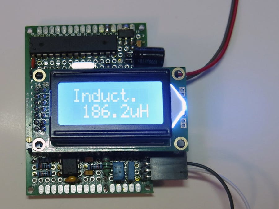
This is another project for inductance meter, now based on famous Arduino micro controller. The main purpose of this project is to highlight the difference between two micro controllers? STM32 and ATmega328P.
UPDATE 01/10/2020
Added sketch to debug the hardware configuration (I_meter_debug)
This program should display 4 parameters:
- "LC" - The period (in timer ticks, 1/16 microseconds) of internal Inductance + Internal capacitor oscillator
- "LCC" - The period of Internal Inductance + Internal capacitor + Calibration capacitor oscillator
- "CAP" - The internal capacitor value, uF
- "IND" - The period of Internal Inductance + External Inductance + Internal Capacitor.
The LCC period should be bigger than LC one. IND period should be digger than LC one also.
First of all, due to less frequency of ATmega328, 16MHz vs 48MHz, the inductance was increased to 1mH (mili Henry, i.e. 10 times bigger) to separate calibration periods, the Li Ci and Li (Ci + Cc). Nevertheless, the lack of frequency sometimes disturbs the measurements, because of wrong calibration and the external inductance value is shown wrong.
Upload the sketch onto the controller and that it is.
On the other hand, Arduino controller has enough free flash memory allowing to turn this project into LC meter if you wish.


Comments
Please log in or sign up to comment.