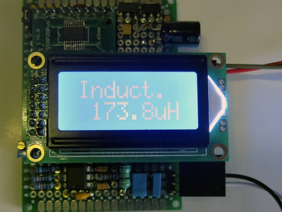
This project is just a "migration" of the LC-meter based on PIC microcontroller to tiny STM32F030F4P6 in tsop-20 case.
UPDATED 01/14/2020
Fixed bug in the schematics
Sometimes we need to check the value of unknown inductor or transformer, but non-expensive multimeter does not allow to check the inductance, only capacitance. So it is good idea to create own non-expensive inductance meter using micro controller.
I have found a brilliant project of LC-meter based on PIC micro controller in the Internet. The central circuit of the schematics is a multivibrator built on fast LM311 comparator that creates non-fading oscillations with the period proportional to square root of LC. Unfortunately, I have no working experience with PIC micro controllers, so I decided to recreate the project on tiny STM32F030F4P6 IC.
To check the value of the external inductor, we make three measurements:
- Short the probes, close the internal L - C circuit, and check the period of LiCi circuit. Let it be tick_LC period.
- Using reed relay, connect the calibrate capacitor, 1000pF (very accurate) to the circuit and check the second period, Li (Ci + Cc), let's say tick_LCC.
- Connect the external inductor to the probes and disconnect the calibration capacitor, check the period (Li + Lx) Ci.
If you do some math, you can find that the value of the external inductance is a function on all three periods and the value of the calibration capacitor.
The first problem was that there were no peaks at all on 7-th pin of my LM311 comparator when specified values of internal inductor and capacitor used. It seems that the oscillation period is too small in this case, so I decided to increase the value of internal capacitor. Unfortunately, the bigger value capacitors have no such precision as one that has 1000pF capacitance. I.e. you can find 1% 1000pF capacitor and only 5% 10-100 nF capacitors. All in all, this project finally used 1% 1000pF (1nF) calibration capacitor and 5% 47 nF internal capacitor.
The second problem was to increase the difference of the first two periods. The original schematics double the second period, because both capacitors were the same value. In this case, when we attach calibration capacitor, we increment the capacitance by 1/47, which is not big. So, the value of the internal inductor was increased also to increase the difference of the two periods: Li Ci and Li (Ci+Cc);
We increase the values of internal components and increased the period of the internal oscillation loop. Now LM311 start working correctly. Furthermore, the bigger value of the internal capacitor allows to measure the external indictor more accurate because the period depends on LC value, so the period increase fast when we increase the L. The second reed relay allows automatic calibration of the internal circuit Li Ci.
As was mentioned the inductance meter is based on tiny STM32 micro controller, STM32F030F4P6. This IC is supported by free software kit from st, CubeMX and system workbench. First of all we use the cubeMX to initialize ou
To check the oscillation period on pin FREQ, we need the accurate clock signal. So we configure the clock of the micro controller as shown on the picture below.
We use the external 16 MHz crystal for the micro controller clock source, then we increase the processor frequency the maximum value, 48 MHz. Then we configure the timer TIM3 in the capture mode to check the oscillation period.
The TIM3 is clocked by the system clock at 48 MHz and counts from 0 to 65535. As soon the falling edge is detected on TI1FP1 (FREQ pin) the current counter saved to the period value and timer reset its value. Brilliant idea from st corp.
You also need the LCD 1602 library for STM32 to build this project. You can download it separately or take it from the project repository.
There are several ways to upload the firmware to the micro controller: you can use.hex file and upload it via STM ST-Link utility or you can recompile the project by using cubeMX and System Workbench tools.
ConclusionThis inductance meter is proven to measure the inductance of 2uH to 400mH with accuracy about 5-10%. Suppose, it is acceptable for home usage and you can have some fun while build and investigate it. Enjoy.


Comments
Please log in or sign up to comment.