


Hardware components | ||||||
_ztBMuBhMHo.jpg?auto=compress%2Cformat&w=48&h=48&fit=fill&bg=ffffff) |
| × | 1 | |||
 |
| × | 1 | |||
 |
| × | 1 | |||
 |
| × | 1 | |||
 |
| × | 1 | |||
| × | 1 | ||||
Software apps and online services | ||||||
 |
| |||||
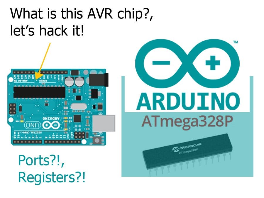
I wondered what's the big black chip on the Arduino board and I knew it's an AVR.
It has been a long while since I wrote my last post, I hope you enjoy this one!
Although I used Arduino a lot and I know it's based on AVR. I actually never had the chance to get a bit under the hood and play directly with the AVR, during my undergrad I had a course on embedded systems and it talked about microcontrollers, those stuff are pretty fun to fiddle with.
This post touches (very lightly, otherwise this is a content of an embedded systems course) on what microcontrollers are, how they are different from your PC and to have a happy ending, we'll control some pins of digital I/O using AVR syntax (hacky stuff, Yaay!).
DisclaimerI use simple terminology that doesn't need any engineering specialization or CS background, as a trade off the concepts are correct but are not necessarily laser accurate. Just enough to deliver the big picture. I won't refer to this assumption in the article for brevity.Microcontrollers
We use Arduino and we love it because it's very simple and gets along with almost everyone who's interested in technology. Although this is enough for day to day maker's use. A maker will always wonder about the internals of the systems they've used after a bit of time.
Microcontrollers are super useful devices, the can be described as simple cheap brains for hardware. For example, the monitor, keyboard, mouse, mobile phone, fridge, TV, car and the telephone network, each of them at least have one microcontroller lurking inside.
Simply speaking, a microcontroller is a mini version of a PC. Let's break this down,
Processor (Brain)A modern PC has a processor that runs on a GHz scale (roughly does some billion "machine" instructions per second). If we look to the Arduino we'll find that it does about 16 Million "machine" instructions per second, that's a scale down of 1000 times. If you're saying that's so slow, I'll tell you that it depends on the application, you don't really need a GHz processor to operate the IR remote for your TV. The advantage is that this makes devices very cheap because they're not resourceful.
Registers and RAM (Memory)During our thought processes as humans, we use our brain a lot, but what would happen if we couldn't remember anything? We don't know what we learnt, our friends, parents,...etc. Life would be impossible to continue this way.
This analogy is true for the microcontrollers as well, besides the processor, they need some sort of memory that they can access swiftly in order to store the values they're performing computations on. Another type of memory is the RAM, we can think of the RAM as some larger memory that's relatively slower to access than registers. As an example, if you're doing some cooking in the kitchen the registers are your what your hands hold and the RAM will be the items on top of the cupboard. You directly use what's in your hands but eventually you must pick up something on the cupboard.
To give you more insight, consider the following code
delay(100);In this case, the value 100 will be stored in one of the registers and the code for the delay function itself is stored in the RAM. The processor is passed each instruction from the RAM and executes the instruction using the values in the registers.
Pins (Limbs)We're almost done, this is the final theoretical part before diving into code. In order to talk with other people, we use our tongues, postures and wave our hands in order to deliver the information that we are communicating. This is the same case with the microcontrollers, instead of having biological limbs they have Pins. Pins as used to read, write information to the outer world.
For example, the Arduino communicates in serial using the serial pins, you find those 0, 1 pins in the Arduino Uno with RX and TX marks that most of us know that we shouldn't be using those in our circuits. Those pins are the ones the microcontroller in the Arduino use to receive information (Rx) and Transmit information (Tx) to other devices (including your PC through the Serial monitor).
A group of pins is called a Port, think of it like each group of our fingers are lumped into a limb (hands / legs). For example, the pins 0 - 7 on the Arduino are on port D.
Pins are bidirectional, in a sense that they can do some output or read input you naturally do this in Arduino by using pinMode(13, OUTPUT); for example.
Let's think a while about this, is it strange? the pin is just a wire, how on earth can it have a direction? Actually, I will not answer this question, it's your quest to find out. I will answer another question instead, I said that pins are wires, how do they remember their direction? is it possible that if I use pin 13 as output that I put 5v into it and then use digitalRead(13) ? (please don't try this unless you know and are happy with the consequences).
So, it seems that we need some memory for the Arduino to remember about pin directions, what about using the registers since they're closest to the processor? that's a good idea! :v
This part might be a bit confusing since we're not used to this in our day to day life, some registers in the microcontrollers are gifted, they have more responsibility than just holding data. Some of them for example control the timers or determine how the baud rate is internally calculated. Registers are 8-bit on the Arduino uno, so, because they're very important, each bit will have a different function depending on the register, those high ranked registers are called Special Function Registers.
Each port has 3 main registers,
- Data direction register DDRx
- Port INput register PINx
- Port Data register PORTx
where x is the port name, i.e. for port C we have DDRC, PINC and PORTC. Note that the bits start from right to left. so the bit on the far most right corresponds to Pin0 in port C
Let's CodeOur circuit will be a simple light switch. A push button connected to pin 6 and an led on pin 7. The LED turns on as long as the button is pressed
For the setup, we want to declare pin 6 as input and pin 7 as an output, this is where pin direction control comes in. To set a pin's direction we use the Data Direction Register (DDR) and since we're using pins 6, 7 they're on port D. To get the final name of the register you append the name of the port to the register so it becomes DDRD
To set certain bits in a register, bit-wise operations are usually used, they're totally different from the ones used in if conditions albeit they look almost similarI won't cover them here and I'll just use binary numbers to make the code easier to comprehend and for educational purposes (albeit a bit harder to read)To set a pin as input we put a 1 in its bit and on the contrary, to set a pin as input we put a 0 in its corresponding bitin the register. (as per the data-sheet)
To set pin 0-6 as input and pin 7 as output.
DDRD = 0b10000000;sidenote that if you accidentally change pin 0 to output will stop the serial monitor from working.
Register variables don't need to be declared, so you don't define DDRD variable anywhere. that's done for you internally ;)
A bit confusing? no worries, what we want to do is turn on the 7th bit in the DDRD register to make pin 7 work as output. Here is the illustration one more time
Writing a value that starts with 0b means that you want this to be treated as a binarybits (explanation from CS50) number not a normal number (integer). Now pin 7 is is output (turned ON) and pin 6 is input (turned OFF). but for the sake of the tutorial, consider that each digit in the number maps directly to a location in the register, the same as with the keys to turn lights on in our rooms, each bit represents a key.
To read the push button input, we need to read the value of pin6, the register that's used to read pins is the PIND register. instead of setting a value, now we want to extract a bit from the register and make sure it's equal to 1. To do this we want to formulate a statement that extracts only the 6th bit.
PIND & (0b01000000)the 0b01000000 is a bitmask because it lets us see only certain bit(s). the & is a bit-wise operator, using this operator will make the expression evaluate to zero only if the 6th bit is 0 in PIND register, otherwise the result is a non-zero value.
This is perfect to use in an if statement, remember that in C only a value of 0 evaluates to false any other positive/negative value evaluates to true. So, the expression that will make the check for us is
if( PIND & (0b01000000) ){
    // The button is pushed (turn on the LED)
} else {
    // The button is released (turn off the LED)
}
We're almost done, what's left now is to actually set the value of pin7 (connected to the LED) when the condition is met, and turn it off otherwise.
To do this, we will use the PORTD register, it's used to write data to the pin. To set pin7 to HIGH we put 1 in the corresponding bit
PORTD = 0b10000000;Similarly, to turn the LED off we set the bit to 0
PORTD = 0b00000000;Note I assume that you're not using any other pins in port D because I'm simply turning off all the other bits, otherwise you have to use bit-wise operators to be able to set a specific bit
Now we can formulate the whole condition that will be placed in void loop()
void loop(){
    if( PIND & (0b01000000) ){
        // The button is pushed (turn on the LED)
        PORTD = 0b10000000;
    } else {
        // The button is released (turn off the LED)
        PORTD = 0b00000000;
    }
}
Phew!, that was quite a dose of information. We're done now.
Buy electronic components on utsource.net.
SummaryWe discussed some of the main components of the microcontroller like the processor, register and ports.
We had a look on how to perform low level IO, which is much much faster than using the Arduino library (in case you're doing a time sensitive application. To check out Arduino's docs on the topic, visit this link where they mention some pros and cons for using AVR syntax.


_3u05Tpwasz.png?auto=compress%2Cformat&w=40&h=40&fit=fillmax&bg=fff&dpr=2)
Comments