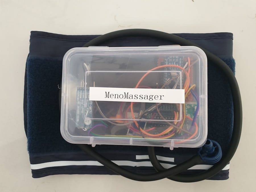
Joint pain and muscle pain are experienced by many women during menopause. I have attempted to build a device that provides relief and helps in reducing joint pain and muscle pain in the hands and legs. I guess every one of us enjoys that moment when a blood pressure reading is taken. The warmth and massaging effect that we feel in our hands when the cuff inflates does feel good right?! The technology is similar! The device will be controlled through a mobile application and will be very easy to use by any middle-aged woman. The fact that it is a low-cost product makes it a really affordable and useful device!
How does it work?The device has two major components, pressure cuff, and the controller unit. When women experience joint pain or muscle pain during Menopause, say pain in the thighs, they will have to just wear the cuff around their thighs and then plug the cuff to the controller unit. They simply have to open an app on their phone and choose whatever pressure and speed they would feel comfortable with and set a timer and click on start. The massager will start and provides a relaxing and soothing massage and relieves them of any pain and make them happier.
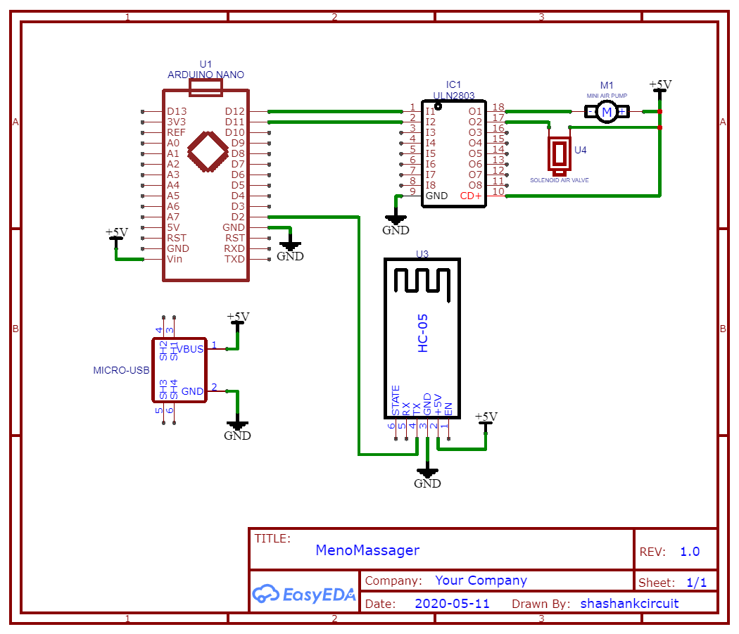
Hardware ArchitectureI have used the Arduino Nano microcontroller board which has an Atmega328P microcontroller and Arduino IDE 1.6.12 for programming in this project(There are newer versions available). For driving the solenoid air valve and the mini air pump, I have used a ULN2803A driver module. This module can take 5V input and can handle up to 500mA on every output pin. For powering the device I have used a power bank, it also works with a 5V 2A power adapter. The Arduino shall give control signals to the driver according to the configurations made on the app. Bluetooth module HC-05 is used for communication with the phone.
A pressure cuff easily available in the pharmacy/surgical store was connected to the mini air pump through a pressure tube which usually comes with the pressure cuff kit.
A solenoid air valve which is also driven by ULN2803A and controlled by Nano acts like a gateway and when activated doesn't let the air out therefore increases pressure within the cuff making it inflate. Also, I salvaged the tube assembly from an old digital Blood Pressure Monitor.
For monitoring pressure, the BMP180 sensor was used. Since this has an I2C interface, it was easily interfaced with Arduino using the four pins( +3.3V, GND, SCL, SDA). The sensor module was put inside a 3D printed housing which has a nozzle for connecting the tube and sealed from all sides for obtaining consistent pressure readings.
The pressure sensing unit, the mini air pump, and the solenoid air valve were tested using the Arduino Nano to make sure it is working before finishing the assembly.
All the components and modules are integrated according to the block diagram. Here the input power source and pressure cuff is an external component and will be outside the housing.
For housing all electronics I have used a plastic box of dimensions 120mm x 70mm x 35mm (l x b x h). I have made some slits for accommodating the cuff connector and micro USB port for power.
A cutout was made to fit the pressure cuff nozzle
All the electronics are put inside this box and the micro USB port is exposed out for power.
All the modules, air pump, and solenoid valve is assembled inside the box.
After assembling all the modules inside the box the box shall be closed using the hooks which were already available on the box.
The Android mobile app was built using kodular.io. This is similar to the MIT App Inventor in functionality, it also has a neat interface and many additional features. After signing up on the website we can go ahead and create a new project.
The project can be configured with a theme, color, name, and other attributes which can also be changed later. The configurations shall be kept default for this project. Then the finish button has to be clicked which takes us to the main dashboard!
The UI is really easy to use with drag and drop blocks and design. The design tab is used for creating a User Interface. Buttons, List Pickers, Time Pickers, Scrollers, and Switches are used for design. Bluetooth client block is used for connectivity with the HC-05 module.
The blocks tab is used to write logic and functionality for the UI design page. The following structure is used to build the blocks:
- Scan Bluetooth devices and display the list of available Bluetooth devices
- Change status from Disconnected to Connected when it successfully connects to the Bluetooth module
- Collect the value set on parameters like pressure, speed and time
- Create a dictionary with a key-value pair and send data through Bluetooth as JSON.
After finishing the design, the.apk file is generated by clicking on Export and saving the.apk file. The file is transferred to the Android phone and installed.
This android application lets the user set all parameters like Pressure, Speed, Time, and Start the device by clicking on the Start button. The stop button is provided to stop the device in case required to stop the device. The user will have to first pair her phone with the Bluetooth module by entering the default pin for HC-05 which is "1234" and keep the Bluetooth ON.
Arduino IDE was used to program the Arduino nano. I have used Arduino IDE version 1.6.12 for this project. The latest version can be downloaded from the Arduino website. The Arduino Nano board is selected by clicking on the Tools> Board> Arduino Nano.
We can add any additional libraries by clicking on Sketch> Include Library > Manage Library
We will need the BMP180 library from Adafruit which is well written and works flawlessly and the ArduinoJSON library.
The code has three main parts, the Serial read part to take in input from the serial port from Bluetooth, The ArduinoJSON parser, and the pressure monitor and control part.
The device becomes activated when there is valid data on the serial port and the attributes are set accordingly
if (Serial.available() > 0) {
    //When Serial data is avaiable on serial port enter this loop
    incomingData = Serial.readString(); // read the incoming byte:
    Serial.println(incomingData); //Print on serial moniotr(For debugging purpose)
Then JSON data received is parsed and values are extracted from their corresponding keys
StaticJsonDocument<200> doc; // 200 is memory capacity in bytes
    DeserializationError error = deserializeJson(doc, incomingData);

    time_rec = doc["Time"]; //Parse and extract time data
    pressure_rec = doc["Pressure"];  //Parse and extract pressure data
    speed_rec = doc["Speed"];  //Parse and extract speed data
The Mini Air Pump and Solenoid Air valve are controlled by making the digital Pins 11 and 12 on Arduino HIGH and LOW alternatively as shown below. The received values are then multiplied with a multiplying factor to map the actual value in terms of pressure, speed, and time.
if (bmp.readPressure() > (pressure_default + (pressure_rec * 3000)))
    {
      digitalWrite(air_pump, LOW); //Pressure cuff deflates
      digitalWrite(solenoid, LOW);
      delay(speed_default_on - (speed_rec * 500) );
    }
    digitalWrite(air_pump, HIGH); //Pressure cuff inflates
    digitalWrite(solenoid, HIGH);
    delay(speed_default_off - (speed_rec * 500));
  }
The data is received in JSON format from the App and then the corresponding values are parsed, Only If the Time attribute is set to more than 1 the device will be activated and is deactivated when the Timer is elapsed. Time is set in minutes on the App and the actual minute value is sent to Arduino.
In the code, a variable called "time_def" is used to activate and deactivate the device. Once the device is activated by making the value of time_def "1", the pressure monitor kicks in and starts its action.
The Mobile App allows the user to set the required pressure by using a scroll bar. She can choose between Light, Medium, and Deep pressure modes. The corresponding pressure value is sent to Arduino Nano through Bluetooth and the required pressure is set. The timing diagram illustrates the functionality of the pressure setting. The pressure value (Light-0, Medium-1, Deep-3) set acts as a threshold and the pressure cuff inflates to that pressure level only. The mapping of pressure value and the actual pressure level is done on Arduino.
Speed can be set on the App by using the switch button. The user can choose between Low, Medium, and Fast speeds which correspond to the time the pressure cuff has to inflate and deflate. When the setting is Low speed, the pressure cuff inflates and deflates at a slow rate. When set to Fast speed the pressure cuff inflates and deflates at a fast rate. The value that will be sent from the app to Arduino for Low, Medium, and Fast Speed setting would be 0, 1, and 2 respectively. The mapping of the speed would be done on Arduino.
For demonstration purposes I have used a ball inside the pressure cuff, we can see it expand and contract.
Further improvements- Include voice alerts for better feedback
- Making a proper ABS enclosure for the device
- Making the mobile App more interactive and include analytics
- Include battery within the device


Comments
Please log in or sign up to comment.