


Hardware components | ||||||
 |
| × | 1 | |||
| × | 2 | ||||
| × | 2 | ||||
| × | 1 | ||||
| × | 1 | ||||
| × | 1 | ||||
| × | 4 | ||||
| × | 2 | ||||
| × | 1 | ||||
Software apps and online services | ||||||
 |
| |||||
The TI-RSLK robot is an educational robotics kit offered through Texas Instruments (TI) is a kit that offers a variety of labs to teach basics in robotics. The kit is used in computer science and electrical and computer engineering courses at various universities.
But what if there could be an add-on to this kit that could teach different engineering concepts? This is the question we tried to answer.
We are a group of 6 electrical and computer engineering students at the University of Colorado Boulder and for our senior project we designed the TI-RSLK solar charging station.
This add-on to TI’s existing robotics kit is designed for students by students to teach power electronics and solar harvesting with hands-on learning. With the growing population and changing environment the world is in dire need of power engineers thinking about how to better incorporate sustainable energy practices into the power grid. Up until now, many engineering programs have relied on a text-book approach to teaching engineering concepts and focused mainly on theory rather than practice, but we are beginning to learn as a society that the best way to teach engineering is with hands-on projects applying the concepts instead of with exams.
Our project is split into two parts: power and autonomous navigation. Within navigation, using encoders with ultrasonic sensors and IR sensors allow the robot to find its way back to the station autonomously. Power is split into 4 subsections: the solar panel, the station, the station PCB, and the robot PCB. These four parts work together to charge the robot batteries in a period of less than a day.
NavigationThe purpose of the navigation system is to make the TI-RSLK robot autonomous. Using ultrasonic sensors and IR emitters, the robot can avoid obstacles and find it's way back to the station. The software flow will be as follows:
Each subsystem is described in more detail below.
IR EmittersEach IR emitter is driven by a square wave which is a multiple of a base frequency. These signals are generated using a timer on the station MSP432. The timer increments at 3 MHz and an interrupt is called when this timer reaches a capture value of 10. The ISR increments a counter and resets the timer. Whenever the counter value is evenly divisible by a multiple of 2, the ISR toggles the corresponding GPIO pins connected to IR emitters.
Navigation AlgorithmsThe robot, after undocking from the station, drives around avoiding obstacles until a low battery voltage is detected. It then orients itself toward the station and drives towards it, avoiding any obstacles encountered along the way. It aligns itself more precisely to the docking port and docks until its battery is fully charged. Once its battery is charged, it begins driving around randomly again. More detailed descriptions of each navigation algorithm in relation to the sensors used are given below.
Returning to StationThe robot initially drives forward some distance, which is tracked by encoders. It then turns and drives another distance. Using the two distances and angle measured thus far, the distance to the station, which forms a triangle with the previous distances, is calculated using the law of cosines. The law of sines is used with this new angle and the previously measured data to calculate the angle to the station.
As long as the robot is continuously performing these calculations using the encoder data, it always knows its distance and angle from the station, even as it avoids obstacles. The dynamic nature of the algorithm ensures that calculating the distance and angle to the station is always the simple case of calculating the side and angle of a triangle.
It should be noted that the angles the robot turns and the angles used in triangle calculations are not actually the same. A simple equation is used in the code to convert between the two.
When the robot sees an obstacle with its front-facing ultrasonic sensor while driving along, it stops and checks for the presence of obstacles to its left and right using its side-mounted ultrasonic sensors. It turns in the direction where there are no obstacles (right if there are obstacles in both or neither directions) until a side-mounted ultrasonic sensor sees the object previously in front of the robot.
The robot then drives forward until the side sensor no longer sees the object, turns 90°, and drives until the side sensor sees the object again and then no longer sees it again. At this point the robot has avoided the obstacle and continues either driving around randomly or heading toward the station.
When navigating with the side-mounted ultrasonic sensors, the robot always drives a small extra distance after the sensor no longer sees an obstacle to account for the fact that the side sensors aren’t mounted on the back of the robot.
Aligning to Docking PortThe robot has two angled IR receivers mounted on its front. When it determines from encoder data that it should be close to the station, it first turns until no IR signal is detected. It then turns again and, once IR is detected, records its current angle using encoder data. It continues turning until IR is not detected again.
At this point, the robot checks the frequency of the IR signal being received. If it is the frequency for the front of the station, the angle recorded earlier is subtracted from the current one and halved to find the angle the robot needs to turn back to orient towards the station. The robot turns this angle and drives until it is mechanically guided and docked to the station. Otherwise, the robot drives forward until IR isn’t detected and repeats this process as many times as needed until the station is found.
The above section describes the design that we utilized for each section of navigation. However, we encountered some problems and were not able to debug in our time with this project and there is plenty of room for further development.
1. The ultrasonic sensors have difficulty detecting obstacles that are not completely flat faced. If some sort of mapping algorithm was developed for obstacle avoidance, this would significantly improve navigation. Furthermore, using IR sensors in combination with the bump-sensors included with the TI-RSLK kit could potentially simplify the navigation process and/or improve it significantly.
2. Battling encoder slippage. We wrote an algorithm that significantly improves the effects of encoder slippage, however, this is a problem that can be eliminated by not relying on the encoder count to perform operations. The robot also incorrectly calculates angles when attempting to drive in a triangle.
3. Improving the docking algorithm. First, the dock function that we wrote is messy and should probably be rewritten in a more concise manner. The docking algorithm is missing functionality to navigate in front of the station and gets stuck in an infinite loop. This both causes the robot to continue running even once it has docked and also the robot loses the IR signal. Furthermore, the robot uses a timer to leave the station and this should be changed to sensing that the batteries are fully charged.
4. The station MSP doesn't open the connection to the robot when it should (this could be an issue with incorrect sample conversions into code).
PowerThe power system consists of two printed circuit boards and a solar panel which allow for solar charging to occur. First, the solar panel is connected to the station board which utilizes Maximum power point tracking to optimize the power that charges the station batteries (two flat-pack lithium ion batteries). Then, the station batteries charge the robot board and the cylindrical lithium ion batteries which power the TI-RSLK robot. An overview of the power system is shown below:
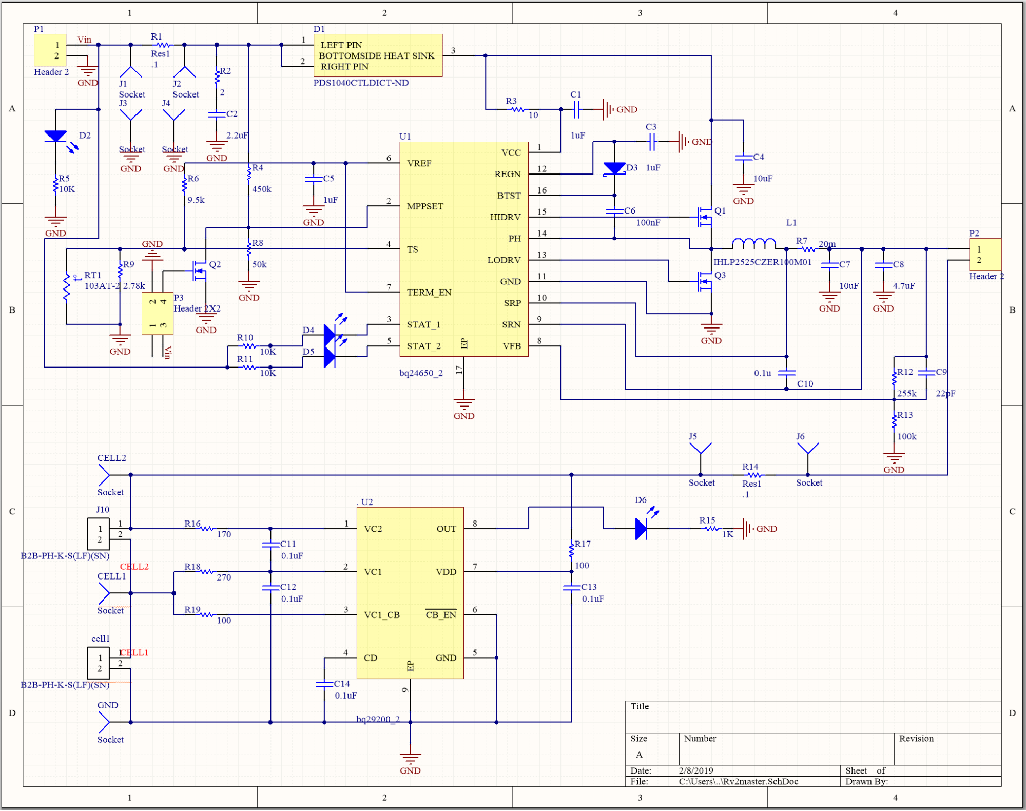
An important part of a system that uses solar charging is the inclusion of a maximum power point tracker (MPPT) because the amount of sunlight is always changing. An MPPT varies a load as sunlight conditions change to extract the maximum power out of a panel. We determined that the BQ24650 is a good MPPT to use for our station board because it is both an MPPT and a battery manager. The robot batteries do not charge straight from the solar panel because the power circumvents the MPPT and the solar panel outputs at the battery voltage. The MPPT algorithm is also hardware programmable. In addition, the battery manager contains overvoltage protection and thermal shutdown to regulate battery voltage and current.
To implement the BQ24650 (solar battery charger), we mostly followed the application schematic at the end of the datasheet because we found that the protections in place would work for our application. The equations from the BQ24650 datasheet that we worked out were:
To implement the BQ24130, we also primarily followed the application schematic at the end of the datasheet, but left the CELL pin floating to configure the chip for a 2-cell input. Additionally, we chose the sense resistor so that the charging current of the robot batteries is limited to 1A.
The MSP432 microcontroller on the station is used to disconnect the station and robot batteries once they become fully charged as well as send square waves of various frequencies to the LED emitters. We wrote all code for the microcontroller in embedded C with the Code Composer Studio IDE.
Solar PanelIn order to meet our requirement of reliably charging our station battery in one full day, we chose to use a 25 W, 12 V solar panel from Newpowa. This is larger than our calculated power needs, as the solar panel will be significantly less efficient than the listed power. Solar panels usually only reach 80% of their specified peak power, and that is only reached when the sun is directly overhead. When the sun is at other angles to the solar panel, the power output is significantly lower. By buying a larger solar panel, we do not have to try to track the sun through the sky, which would require a lot of mechanical components. Overall, the larger solar panel will help us ensure we meet our requirements, even under less-than-ideal conditions, and we can consider reducing the panel size in later iterations of the design if we find the wattage to be excessive. When choosing the type of panel, the three main types of solar panels were considered: monocrystalline, polycrystalline and thin film. Monocrystalline was chosen, as it is the most efficient of the three, and not much more expensive. By having a more efficient panel, we can reduce panel physical size, which will reduce shipping costs and overall system size. The Newpowa panel has dimensions of 22.67in x 14.01in x 0.91in, and a weight of 4.23 lbs.
We tested our solar panel on a cloudy day and computed the following IV curve:
Even on a cloudy day, one amp of current draw is seen from the solar panel which is adequate current to charge the station batteries.
Station DesignThe station will host our solar panel, power transfer connectors, and IR emitter. The front panel of the station will be 3D-printed using ABS filament, and the rest of the station will be constructed using clear acrylic. This will cut down on print time, along with allowing students to see the PCB and other components inside the station. The front panel features a guidance funnel to help with docking by guiding the robot to the power connector. This design was based off of similar docking designs for other robots. In addition, the station is smaller than the solar panel and sits inside the lip on the edge of the panel. By doing this, the rain will drip off the side of the panel rather than running into the station, thus keeping all the electronics dry.
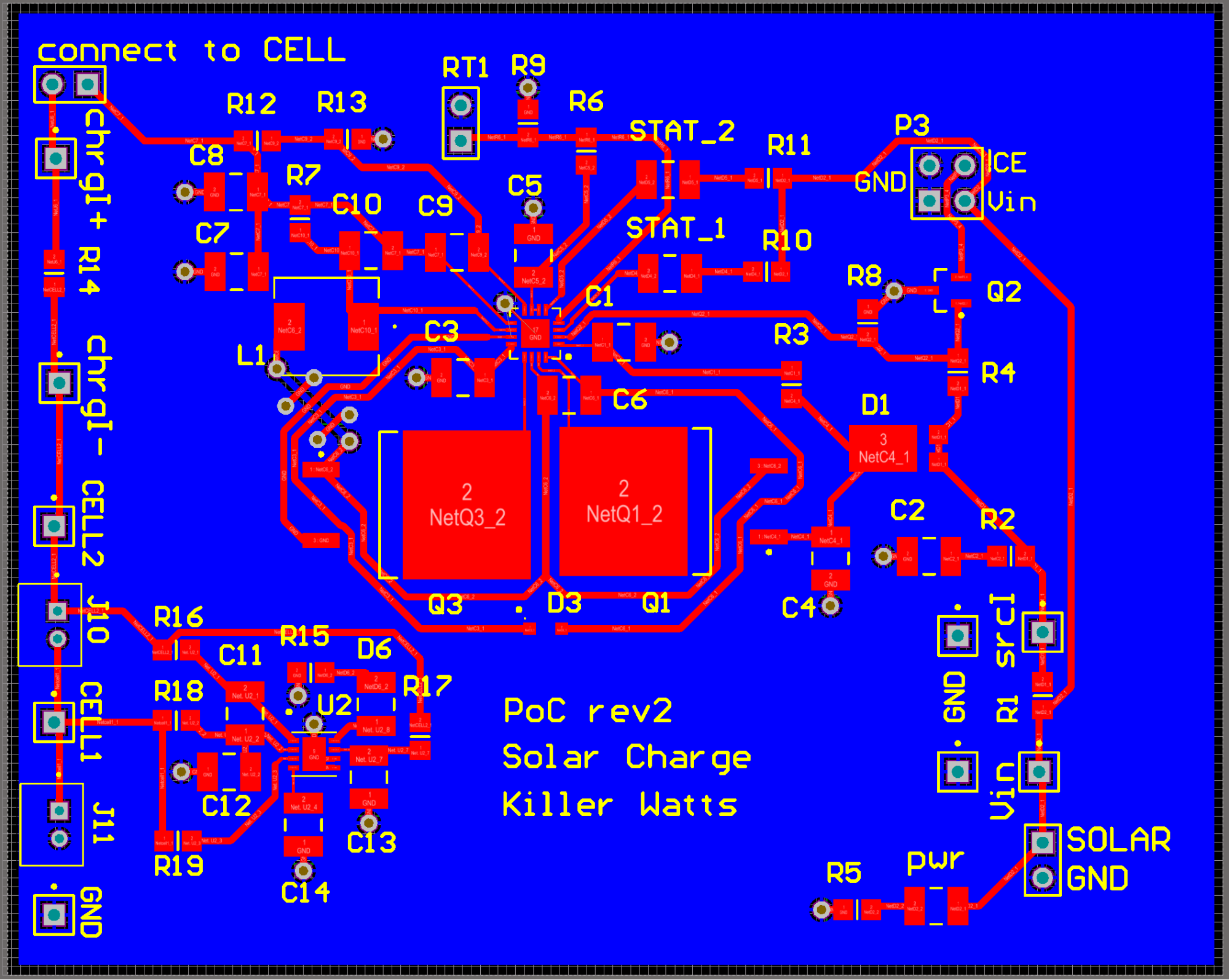
Docking: Power Transfer ConnectorIn order to transfer power between the station and robot, we implemented a mechanical spring clamp connection as seen in Figure 8. On the station PCB, we had four conductive pads, one pair for each of the positive and negative terminals of the batteries. Using ⅛” copper sheeting, we created rails that are soldered to the station pads. These rails will open out into funnels, which guide the robot’s bent copper loops into the terminals. As the loops enter the terminal, the loops bend slightly, making a tight connection. Testing was performed to ensure the connection could transfer power at the desired voltage and current, and to make sure the connections worked mechanically and will withstand repeated use.
Power Improvements and Opportunity for Further DevelopmentSimilar to navigation, we were unable to successfully implement our full charging system. Opportunities to improve charging are described below:
1. Choosing better batteries. The station lithium ion flatpack batteries worked very well, however, the cylindrical lithium ion batteries we used for the robot batteries did not work. We purchased four batteries and once we implemented all of our power circuitry, the batteries were drained below their safe operating point in a very short amount of time. The batteries used in this project should be further researched.
2. Exploring MPPT. Optimizing this chip with our panel is something we did not have a chance to implement. Once the station is fully functional, this can be explored by charging the station under different conditions and testing how the MPPT can be used to control the power draw from the solar panel.
3. Improving copper connection. Future groups should look into refining the copper docking connection by making it easier for the robot to dock. At times, the momentum of the robot would push it up over the contacts, which we solved by putting copper over the top of the contacts. The robot would still sometimes not dock correctly, though, so finding a better way to funnel in the connections would be a good thing to look into.
4. Improving station PCB. Once the robot was docked with the station, we encountered a problem where the LEDs on the station indicated that charging was occurring when no charging was occurring. This can be debugged by looking at FETs with board under power and potentially replace with FETs used on BQ24650 EVM. Otherwise, the station board can be made operational with power supply first and then with solar panel. Next, get the MSP interfacing with current sense chip and op-amp buffer to monitor station battery voltage and current, have MSP turn off and on hotswaps to output rails at critical battery states, and use FTDI chip and MSP to log battery current and voltage data on computer and use Python (or your favorite coding language) to plot station battery charge/discharge in real-time.
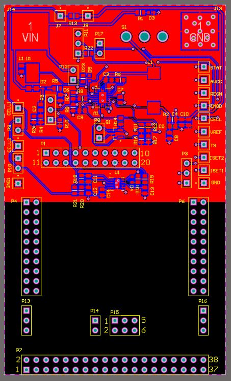
5. Improving robot PCB. The robot boards is not fully functional. Possible next steps are to run a test in which robot batteries charge through the robot board, watch battery charge current and voltage as it goes from a “charging” to “charged” state, monitor status LED of BQ24130, and add a resistor divider and op-amp circuit to monitor robot battery voltage on launchpad MSP.
6. Flesh out power budget. Determine the power draw of each subsystem and different charging modes of standard operation.
Robot Power Circuitry
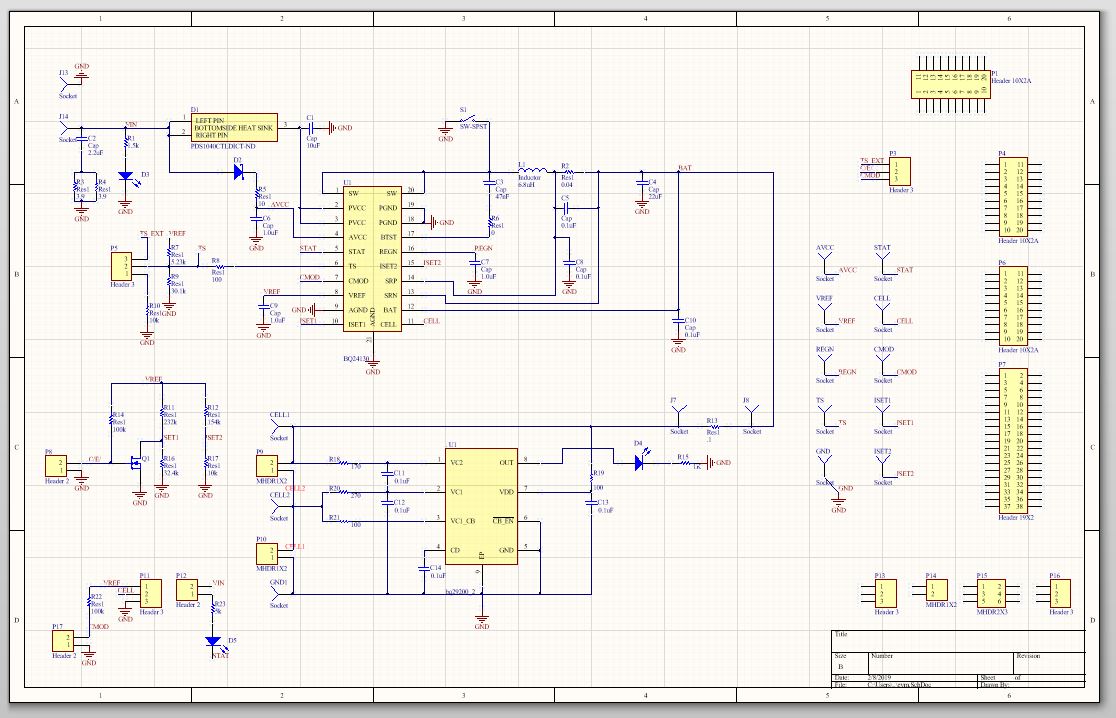
Station Power Schematic


Comments
Please log in or sign up to comment.