


Hardware components | ||||||
 |
| × | 1 | |||
 |
| × | 1 | |||
| × | 1 | ||||
 |
| × | 1 | |||
| × | 1 | ||||
Hand tools and fabrication machines | ||||||
| ||||||
| ||||||
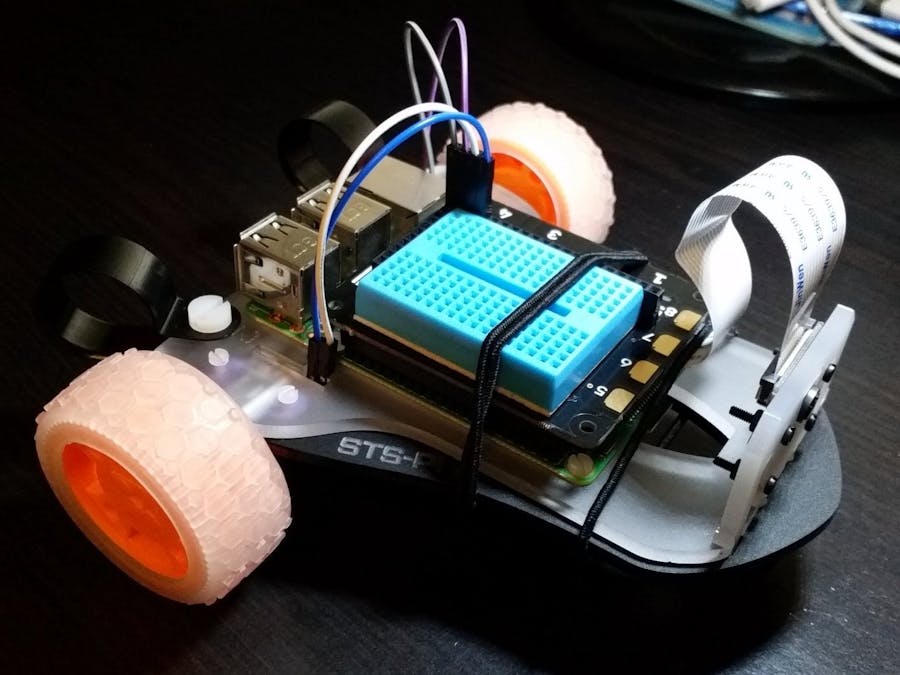
In this tutorial, I will show you an easy step-by-step guide on building your very first roving robot!
Step 1: Components- Raspberry Pi Model 3B
- Pi Cam module
- Pimoroni STS-Pi Robot Kit
- Pimoroni Explorer HAT Pro
- USB Power Bank (Preferably cylindrical shaped)
You will want to remove the protective films from the acrylics with the help of a pair of handy tweezers.
Step 1: Attach your Raspberry Pi to the chassis- Align the white acrylic piece against the black acrylic piece with the logo on the black acrylic piece facing up
- Place your Raspberry Pi on top of the aligned acrylic pieces
- You will be using the 4 x M2.5 10mm bolt and nut to secure your Raspberry Pi to the chassis
- Using a flat-head screwdriver, secure the nuts and bolts in place.
- Place the motor in this particular orientation, taking care to align the motor within the spaces
- Place the motor mount with the Pimoroni logo facing upside down (inside) like so
- You will be using the 4 x M2 8mm bolt and nut to secure the motors and motor mounts to the chassis
- A handy tweezers can easily pick up the nut and you can align it in the hexagonal hole in the motor mount
- Use a flat-head screwdriver to secure the bolt in place and do the same for the other side
- Find the caster wheel, spacers and 2 x M2 16mm bolt and nut. The spaces are used to build height so that the chassis will be perfectly balanced once the wheels are attached.
- Insert the bolt into the caster wheel
- Insert the 3 spaces through the bolt and insert the remaining bolt on the other side
- It should look like this when properly done
- Attach the combined pieces onto the front two holes for the caster wheel
- You should see the bold sticking upwards
- A handy tweezers can easily pick up the nut and you can align it in the hexagonal hole on the white acrylic piece. Use a flat-head screwdriver to secure everything in place.
- Attach the two wheels, taking care to align the semi-circle holes
- Attach the camera mount to the white acrylic piece
- Remember to attach your Pi Cam at this stage! Take care to align the metallic side of the cable to face the same direction as the camera. Once inserted, push down on the connector on the two ends to secure it.
- By default, the Explorer HAT Pro comes with a miniature breadboard
- Align and attach the miniature breadboard to the Explorer HAT Pro
- Align and attach the Explorer HAT Pro to your Raspberry Pi GPIO pins
- You are almost done!
- Attach the male-to-female jumper wires from the motor pins to the motor pins on the breadboard. Don't worry about which motor it is, you can adjust it once you have the program up and running later.
- Make sure to do the same for the other motor
- Connect your USB Power supply to the Raspberry Pi. We are almost there!
We will be using the STS-PiLot remote control web application created by Mark Dammer in his Github repository.
You can either SSH or use VNC Viewer to access your Raspberry Pi interface. There are many online guides and Youtube videos to illustrate how to do it.
Open up Terminal on the Raspberry Pi and install the required dependencies (Picamera, Flask, Gevent, Simplejson) by executing this command.
sudo apt-get install python-picamera python-flask python-gevent python-simplejson
Next, you need to install the Explorer HAT python library as found in Pimoroni's Github repository.
In Terminal, execute this command to install Explorer HAT python library.
curl https://get.pimoroni.com/explorerhat | bash
Now, clone the STS-PiLot project by executing this command.
git clone https://github.com/mark-orion/STS-PiLot.git
Once done, cd into the directory using
cd STS-PiLot
Run the program using
python app.py
Within seconds, the program will be started up. You can access the web application on your desktop or mobile phone browser by going to
http://ip_goes_here:5000.
For example, mine is http://192.168.1.100:5000Step 7: Enjoy :)- The controls on the left hand side (Red, Orange, Yellow, Green, Yellow, Orange, Red) controls the left motor and vice versa.
- Green stops the motor.
- Yellow moves the motor by the smallest speed.
- Red moves the motor by the largest speed.
- Buttons above the green button moves the motor forward.
- Buttons below the green button moves the motor in reverse direction.
- If the left hand side controls moves the right motor, you will need to switch the jumper cables connected to Motor 1 to Motor 2 or Motor 2 to Motor 1, depending on your set up. For mine, the left motor is connected to Motor 2 and the right motor is connected to Motor 1.
- The emergency "Stop!" button in the middle stops all motor movements.
- The buttons labelled 1, 2, 3, 4 corresponds to the touchpads / LEDs on the Explorer HAT Pro.
- 1 and 2 (Blue and Yellow) controls the LED.
- You can trigger a shut down by pressing 3 then 4.
- The "HUD" button toggles the HUD display overlay on the live video feed.


Comments
Please log in or sign up to comment.