Simple problems have simple solutions.
Let's say we want to read 4 potentiometers (or variable resistors), and 3 buttons for some reason, and make those inputs light up a LED based on its value. We can do this by writing a few lines of code, setting 7 inputs, 4 of them analog and 3 digital ones, right? But as the title of the project, I want to use the CD4051 IC (integrated circuit) to channel the 7 inputs to output to only 1 pin! This is called multiplexing, and it's a very useful tool when trying to save on wiring, space, or efficiency. I want to show that you don't always need a microcontroller to do simple tasks, and you can actually do it with no memory or clock involved.
The chip I'm using has a layout of this:
My goal is to go through the process of doing research, prototyping through schematics and breadboards, and then finally creating a final soldered on product. This is the steps I took to do that.
First, I had to do research on the IC to make sure I knew completely how it worked so I didn't break the physical one.Research is very key when creating any type of circuit, especially if you don't know how to make it. I scanned the datasheet to make sure I understood every pin, and how it worked. From this, I learned that there are 8 different inputs/outputs that can channel through a singular input/output on pin 3 of the IC. To select it, I put high or low voltage on pins 11, 10 and 9, or A B and C pins respectively. This turns out to 8 different combinations, as you have 2 to the exponent of 3 inputs (2 to the exponent of the number of inputs you have). This will make it so whatever decimal value it is, it will channel through that pin. (100 will channel through the number 5 pin). I also figured out that INH must be always on low for the purpose of our project, since this makes all the pins enabled when set low. After all this information, I figured out what everything did and was to start wiring. Research like this is very important to make sure you aren't lost and guessing and checking! This is the link for the datasheet I used.
Second, making a prototype with a breadboard. This is where it gets messy.After I finished making all necessary connections, making sure everything was wired properly, I made it neater so that it wasn't a jumble of wires (and also so you guys can actually see what's happening).
With this, you can actually see all the wiring. The white wires represent what I used for the select pins, connected to A, B, C in the order of the combination. Yellow wires are digital inputs, and blue wires signal the analog inputs. I used red wires for power, and black wires for ground (standard). Although not that clean, 330ohm resistor was used with the LED and 10k pull-up resistors were used with the buttons. I only used channels 0, 1, 2, 3, 4, 6, 7, skipping the 5th channel. Here's a short video to show you how it works:
As you can see, my selector pins choose which input I take on, and depending on the binary number it is. It changes what gets outputted to the LED. I've finished prototyping on my breadboard, and it works beautifully! Time to move on.
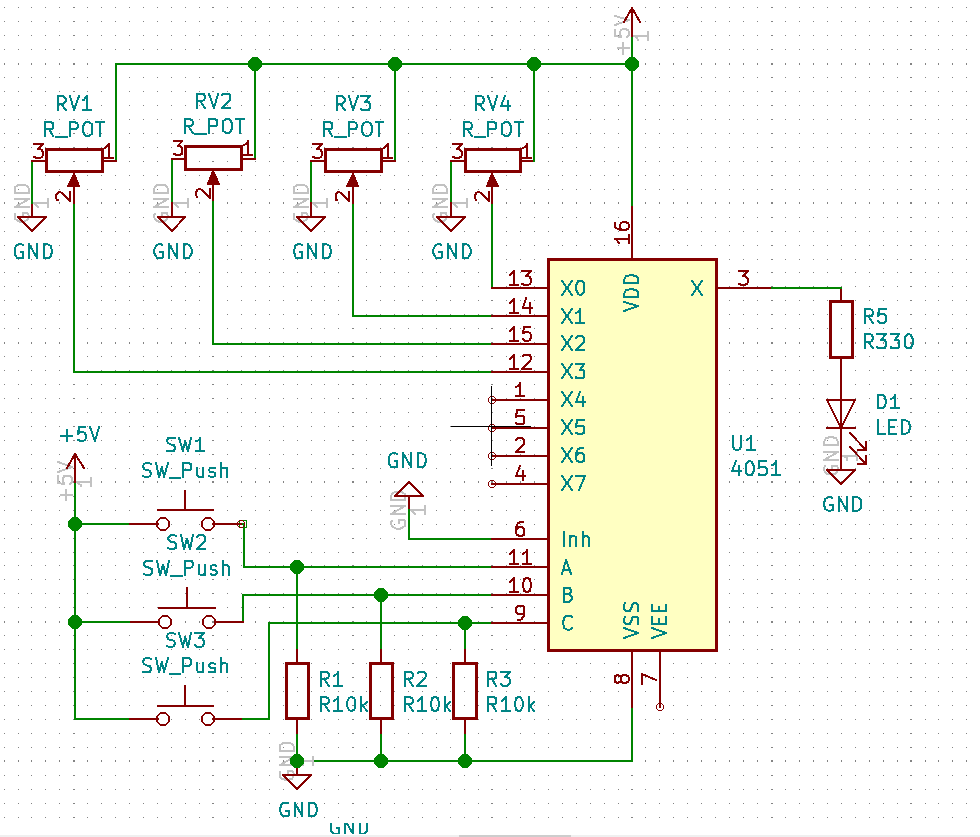
Third, time to create a schematic to solder.To make it easier on myself, I created a schematic on KiCad to build out how I wanted the circuit to look like. I decided to take out the 3 digital inputs for simplicity sake, and put only the 4 potentimeter inputs to pins 0, 1, 2 and 3. This is how it looked like:
Once putting it on a schematic, it allows it to be very easy to transfer to a solderable breadboard. All I need is some solder and an iron now.
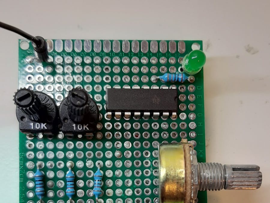
Finally, soldering it together.This process is pretty complex, and there are multiple guides and videos online that can go more in-depth in this process. But, basically, I put in the components, soldered them so they didn't move, and connected all the components together. This is what I ended up with:
As you can see, this is a lot nicer than even the nicest breadboard connections. This is because all the connections are underneath the breadboard, making it invisible to those who are looking above.
A complete product.Finally, I went from research, design and prototyping, to a final product on a solderable breadboard. I could go a step further and make my own PCB, but for this project, I'm not going to go there. With this project, I'm showing you that not all projects need a microcontroller. Sometimes, you can go as simple as just a single IC to get what you want done. This project was pretty cool, and I hope you try this at home too!


_4YUDWziWQ8.png?auto=compress%2Cformat&w=48&h=48&fit=fill&bg=ffffff)


_Ujn5WoVOOu.png?auto=compress%2Cformat&w=40&h=40&fit=fillmax&bg=fff&dpr=2)
_3u05Tpwasz.png?auto=compress%2Cformat&w=40&h=40&fit=fillmax&bg=fff&dpr=2)
Comments
Please log in or sign up to comment.