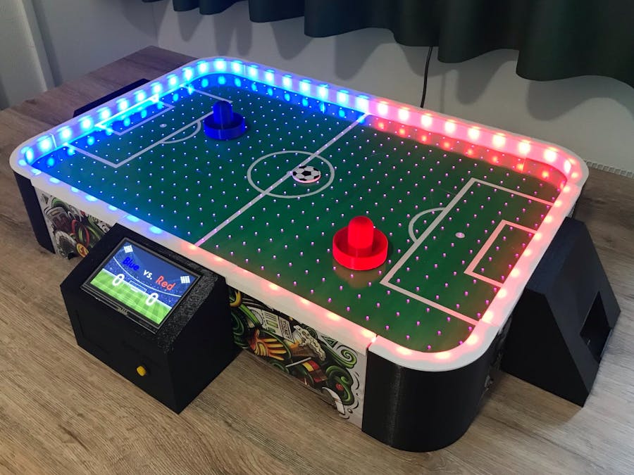
As a part of my exchange programme in Creative Design & Technology at Saxion University in the Netherlands, I created an Air Football. The product is a result of project on 8 weeks, and I chose to make my showcase as a complete DIY tutorial which ended up in this post.
The project's purpose was to extend both creative and technical skills which I did by ex. researching, ideating, developing concepts, user testing, learning SolidWorks, learning how to work with a Nextion display, and furthermore extending my skills in 3D printing, laser cutting, programming in Arduino IDE, and much more.
The product has still place for improvement. An example of this is the usage of delay in the Arduino code which caused that the light show and animation can't be displayed simultaneously.
If you know how to solve an issue like this or have think about other things that can be improved, you're more than welcome to comment suggestions, solutions or use the post as a base for your own project/product post.
Tutorial VideoStep by Step GuideStep 1: Downloading
Start off by downloading the provided zip-files in the bottom of the page. These are divided into four topics:
- Technical drawings - files for experienced users who wants to draw or modify parts themselves.
- 3D prints - STL files ready to 3D printed.
- Laser cuts - SVG files ready to be laser cut.
- Nextion setup - files to upload to the Nextion screen to display score and animations.
Furthermore you need to download Nextion Editor. This is a open source software to setup and upload code to Nextion displays. You can download it through the link below:
https://nextion.tech/nextion-editor/
Step2:3Dprinting
Prepare the STL files for 3D printing by importing them into a matching slicer depending on your type of 3D printer (ex. Ultimaker Cura or PrusaSlicer) and export the g-codes, so they can be placed on a SD card.
All the files are made, so no support is needed, but make sure you orientate the STL files in a suitable way for 3D printing. With some files you might have to add brim to secure that the part doesn't fall over during printing (ex. boundary 2 & 3 and corners).
Step3:Lasercutting
Open the SVG files in a vector graphics editor (ex. Adobe Illustrator or Inkscape) and send them to your laser cutter. Make sure you modify the files into your laser cutter's preferable settings (ex. line color and line thickness).
You can cut all the parts, besides the game board top, in wood (ex. plywood or MDF). The game board top needs to be a material with a smoother surface to provide a good "floating" of the puck (ex. PMMA (acrylic) or PC (polycarbonate).
Furthermore, you need to check with the technical drawings, so you cut the parts in the right thickness. You can also cut some parts multiple times and then glue them together to accomplish the right thickness (ex. the game board lists).
Step4:Printingstickers
If you have access to a Roland sticker machine, you can send the eps-files directly to the machine and print them right away. If not, you need to open the files in a vector graphics editor and adjust them to the settings for your sticker machine.
If you don't have access to a sticker machine at all, you can also personalize the frame yourself by ex. painting the frame or engrave something with the laser cutter.
Step5:Painting
Next step is to paint the game board in a football theme. If you cut the game board in plywood or MDF, you can use acrylic paint.
Begin with painting the game board green and then sketch and paint the white lines. Use painters tape to get straight lines and you might have to paint both the green field and the white lines a couple of times to cover the wood completely, but make sure to let it dry sufficient in between. After painting you might have to put a nail through some of the holes if paint covered them.
If you are experienced and have accesses to a sticker machine, you can also experiment with creating one sticker for the game board instead of painting it - but be sure that you align all the holes in the game board to maintain a sufficient air flow.
Step6:Assemblinggameboard
To assemble the game board you need the following parts:
- Game board top
- Painted game board
- Lists 1, 2 and 3
- Game board bottom
If you cut the lists in multiple pieces to achieve the right thickness, start by gluing those together with wood glue. When they are dry, glue them to the game board bottom. If you game board is bending a little, you must attach small pieces of wood the middle, so the game surface ends up level.
Hereafter you have to glue the game board on top of the lists, so the room for air is sealed around the edge. To make sure of this, put something heavy on top over the night.
Step7:Assemblingframe
To assemble the frame, you need to parts below:
- 2x Side 1
- 2x Side 2
- 4x Corner
Start off by gluing the corners to side 2 with super glue and then attach the side 1 afterwards. Check that you orient the corners and sides right and if the game board can fit within the frame before you start gluing.
Step8:Soldering
Now it's time for soldering the following components, so the connections becomes permanent:
- Battery holder (8xAA) to fan
- (An Arduino shield if you don't have a pre-assembled one)
- Line trackers
- Momentary switch
- LED strip and external power supply
Be aware that you have to attach a boundary 1 to a side 1 and pull wires through before soldering pin headers and external power supply to the LED strip, so it ends up looking like the images below.
Solder afterwards the rest of the mentioned components. Do yourself a favour and use different and consistent colors of wires (ex. red for 5V and black for GND) - it makes it a lot easier when you assemble the circuit later on. Use furthermore some heat-shrinkable tubing to protect the soldering.
Step9:AttachLEDstripandboundaries
Begin with mounting boundary 1, 2, and 3 to the frame, but don't use glue. Use ex. double sided tape, so you always can access the LED strip if something goes wrong.
Afterwards, turn the frame around and carefully place the LED strip in the gap around the frame and stick it to the boundary by peeling off the tape. When it's done, you can turn the frame around again and attach the boundary 4's to complete the boundary.
Step10:Assemblingframeandgameboard
Start with placing the game board top on top of the game board and fix it with ex. nails, so it doesn't slip when you turn it around. Now, turn the game board around and place it in the frame, so it's resting on the boundary's underside.
Find hereafter some scrap wood, lists or something similar and glue it to the frame and game board bottom, so it can act as "shelf support" when the product is turned around again. Make sure you let it dry for at least 24 hours before you flip the product.
Step11:Attachstickers
With the table assembled, you can now attach the stickers on the sides of the frame. Before doing this, make sure to have something near by that you can smooth out the sticker with, so the adherence is good. (ex. a credit card).
Step12:Attachelectroniccomponents
It's time for you to place the following components in their mounts:
- Nextion screen in display mount
- Momentary switch in display mount
- Line trackers in goal slideways
Be careful not to brake the snap fits when mounting the Nextion display as well as not damaging the line trackers when pushing them in.
Step13:Uploadingcode
Start by uploading the Nextion setup to the display. This can be completed in two ways and it's up to you to pick. The first one is fast, but requires a micro-SD while the other is slower but only requires your Arduino:
1. Export the Nextion setup as a tft-file, place it on an EMPTY micro-SD, insert it in your Nextion display, power on the display by ex. using your Arduino, and the uploading will start shortly after.
2. Upload an empty code to your Arduino, attach the display to the TX and RX port on the Arduino, power it on, and upload the setup through the uploading option in Nextion Editor.
When the Nextion is ready, you can upload the Arduino IDE code to your Arduino. If you used the second method above, make sure to disconnect the Nextion display from port TX and RX as these ports are used to upload code to the Arduino.
Step14:Attachmissingcomponentsandassemble electrical circuit
Begin with mounting the fan and its battery holder to the game board buttom. Now, turn around the product and attach the goal slideways and goal covers to the frame. As with the boundary, don't do it permanently, so you always can accesses the line trackers.
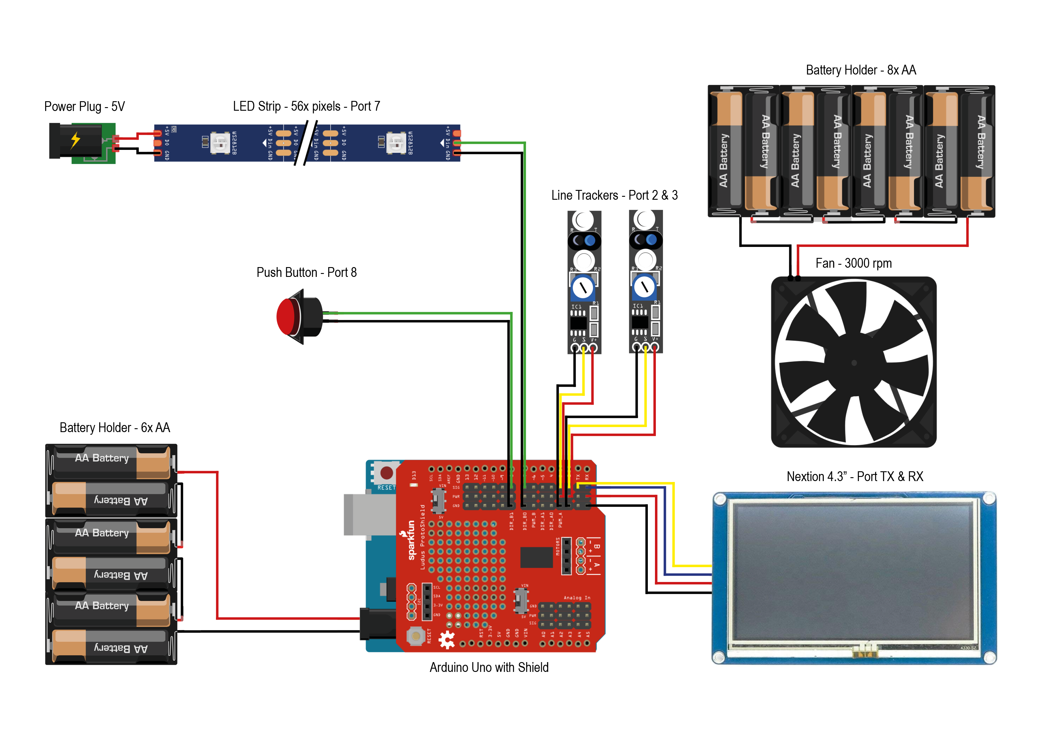
You can now place your shield on your Arduino and connect the components' wires. Remember to check the Arduino code or the schematic, so you connect to the right ports.
Step15:Havefun!
You did it! Be proud and have fun with playing.
Thank you for following the tutorial.


_ztBMuBhMHo.jpg?auto=compress%2Cformat&w=48&h=48&fit=fill&bg=ffffff)


Comments
Please log in or sign up to comment.