This is actually a derivative work from one I found on the web. Just needed to get that out of the way. The original project can be found at: http://lazyelectronics.com/index.php/en/item/3-battester-en
OverviewI have, for a long while, avoided the use of Li-Ion type batteries, owing to the cost and special charging profiles needed. Now that the technology is more mature, I am venturing into their use.
Since my supply of cells will be primarily used stock from various recycle streams, I needed to come up with the tools to test each cell. With that in mind, here's my derivative of this tester.
What I didThe main changes I did are the 20x4 LCD rather than buying a Nokia 5110 that the original author used. I also used the I2C/TWI/SPI interface board for the LCD screen.
Note that the SCL and SDA pins are NOT broken out on the pro mini, they are on the A5 and A4 pins, as noted in the sketch.
Any MOSFET capable of 2.5A constant current or better can be used, best to use one with the lowest Rds on that you can. The one used here actually has a fairly high Rds on of 2.4 Ohm typical. This may actually skew the mAh results. This means that my cells may have a slight bit higher storage capacity than indicated. I had these on hand, left over from a previous project. This particular HEXFET/MOSFET is SMD, but the gate and source pins line up with the .1" spacing on a protoboard. Easy to solder, and even gives a few vias under the drain tab to add a heat sink under the board if needed.
Bad pic, and bad solder job... got it twisted a bit. The resistor is a pull-down on the gate.
The odd headers for the speaker and LCD are recycled from an old printer I tore apart. I used a 6 position female header section for the load resistor, so I can change the load if I need to. I just have to remember to change the code to match whatever I use. 3 position on each end are paralleled, so I can match resistance to whatever load mA I want to use according to the type of cell I'm testing.
Lower right screw block is for 5V power in, upper left block is test cell connection.
The rat's nest of point to point wiring to make the connections. Maybe I should have used several different colors to make it easier to trace should I have a problem later on.
The I2C/TWI/SPI interface board. Cheap on eBay, or Aliexpress, as long as you don't mind waiting 4-6 weeks for delivery. Can be bought anywhere worldwide online.
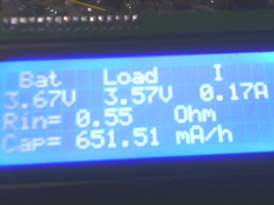
Second view of the LCD, showing the changes from the title image.
Still to do is a case for it, might even need to change the screw blocks out for something else.
ConclusionsAnother thing I'm currently working on in this project is changing the button routine from polling to interrupt driven. I'm not a huge fan of using the delay function in coding unless absolutely needed. In this case, there are better ways to code for button presses. I'll also be looking for better ways to update the LCD.
If you build one of these, and make changes to the code along these lines, please let me know. We can compare notes, and make this a better project!


_3u05Tpwasz.png?auto=compress%2Cformat&w=40&h=40&fit=fillmax&bg=fff&dpr=2)
Comments
Please log in or sign up to comment.