


Hardware components | ||||||
 |
| × | 1 | |||
 |
| × | 1 | |||
 |
| × | 2 | |||
 |
| × | 1 | |||
 |
| × | 1 | |||
 |
| × | 1 | |||
Software apps and online services | ||||||
_4YUDWziWQ8.png?auto=compress%2Cformat&w=48&h=48&fit=fill&bg=ffffff) |
| |||||
Hand tools and fabrication machines | ||||||
 |
| |||||
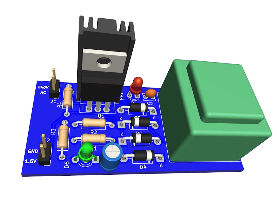
A power management integrated circuit (PMIC) is utilized to supply the necessary power to complex electronic circuits. Designing a primary independent circuit with less low-power electronic elements requires a separate independent power source or a voltage regulator circuit. Therefore, This article will guide designing a primary 1.5V DC power supply circuit, constructed with the help of an IC LM317, thus giving a regulated constant power supply of 1.5V DC. Typically, the primary 1.5V DC voltage controller circuit is utilized on any circuit or device that needs a 1.5V DC steady power supply. The 1.5V DC circuit changes 230V AC to 1.5V DC using a stepdown transformer, a voltage controller IC LM317, and a bridge rectifier.
Circuit Diagram- 10uF, 10V Polarized capacitor, small US symbol C1 C_Radial_D4.0mm_H7.0mm_P1.50mm
- 0.01uF Unpolarized capacitor, small symbol C2 C_Disc_D3.8mm_W2.6mm_P2.50mm
- 1N4007 1000V 1A General Purpose Rectifier Diode, DO-41 D3, D4 D_DO-41_SOD81_P10.16mm_Horizontal
- RED LED Light emitting diode, small symbol, filled shape D5 LED_D3.0mm
- GREEN LED Light emitting diode, small symbol, filled shape D6 LED_D3.0mm-3
- 240V AC Generic connector, single row, 01x02, script generated (kicad-library-utils/schlib/autogen/connector/) J1 PinHeader_1x02_P2.54mm_Vertical
- 1.5 V DC Generic connector, single row, 01x02, script generated (kicad-library-utils/schlib/autogen/connector/) J2 PinHeader_1x02_P2.54mm_Vertical
- SK_95_25_STS_TO_220 MP1 HSINK_SK_95_25_STS_TO_220
- 330R Resistor, small US symbol R1, R4 R_Axial_DIN0207_L6.3mm_D2.5mm_P10.16mm_Horizontal 470R Resistor, small US symbol R2 R_Axial_DIN0207_L6.3mm_D2.5mm_P10.16mm_Horizontal
- 100R Resistor, small US symbol R3 R_Axial_DIN0207_L6.3mm_D2.5mm_P10.16mm_Horizontal
- Transformer_1P_1S Transformer, single primary, single secondary T1 Transformer_Breve_TEZ-22x24
- LM317_TO-220 1.5A 35V Adjustable Linear Regulator, TO-220 U1 TO-220-3_Vertical
This circuit is designed to transform 230V AC into 1.5V DC, requiring a stepdown transformer to convert high-voltage AC to low-voltage DC. A 230V AC to 6V AC output step-down transformer is utilized in this case. The 6V AC supply from the transformer's secondary winding is directly connected to the Bridge Rectifier module. Using either a bridge rectifier module or four 1N4007 diodes arranged in a bridge rectifier configuration is possible. The 6V AC is then converted into a 6V DC supply, which is initially unfiltered. This unfiltered DC is subsequently directed to the filter capacitor C1 for smoothing. After filtering, the DC is fed into the LM317 Regulator IC (in a TO-220 package). The LM317 IC has three terminals. Terminal 1 (Adjust) and terminal 2 (Output) are linked to feedback resistors R1 and R2. By adjusting the values of these two resistors, the output voltage can be set to any desired level within the range of 1.25V to 37V, provided there's sufficient input voltage supplied to terminal 3. The circuit can deliver output currents of up to 1.5 Amps. The output voltage for the LM317 is calculated as;
The constant regulated 1.5V DC power supply is achieved as output after filter capacitor C2. Independent circuits typically use LED indicators to determine the input and output voltage conditions.
1.5V DC Power Supply Circuit Diagram With Indicators
This particular circuit's design, construction, and working are similar to those without indicators. However, two LEDs are introduced to show the voltage for this one. The red LED shows the input voltage, while the green LED indicates the output voltage from the LM317 regulator.
The LM317
The LM317 is a versatile three-terminal voltage regulator capable of providing an output current of up to 1.5 amps and an adjustable output voltage ranging from 1.25V to 37V.
LM317 Pin Configuration
ADJUST pin is the adjustment pin for output voltage and connects to a resistor divider to set Vo. The INPUT pin is the supply pin. The OUTPUT pin is the voltage output pin.
Fabricating such a board prototype using a breadboard is a challenging task. It requires a lot of time and expertise to achieve it. In the modern world, the advancement of technology has made the process smooth. The arrival of automatic systems such as the pick and place plus super soldering systems has made the process quick and exciting. The technology has further reduced the waiting time and improved the quality of the generated boards. Mass production has been attained in the best way possible. All these quality features and benefits are what make PCBWay the world leader in the area of PCB fabrication. The company guarantees returns for your money, quick and quality production, the best customer promotions and offers, and saves time and money. At PCBWay, you can order your board from the comfort of your home by visiting the PCB Instant Quote Page, placing your order, adding your favorite collection point, and waiting for it to be delivered within seven days.

_Ujn5WoVOOu.png?auto=compress%2Cformat&w=40&h=40&fit=fillmax&bg=fff&dpr=2)

Comments
Please log in or sign up to comment.