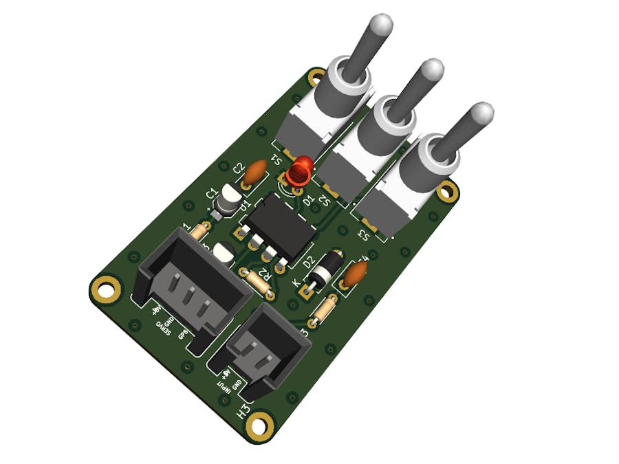
Servo motors, also called rotary or linear actuators, are designed for minimal control of angular or linear points, acceleration, and velocity. Servos can have sensors for feedback, and signal feeds for position control. Different-sized and voltage-rated servo motors are available. All servo motors work similarly depending on requirements, features, and output mass variance. These motors are ideal for motion or rotation depending on mechatronic needs and are widely utilized. A servo motor driver circuit targets sub-miniature servo motors.
Circuit Requirements- C1 1 220uF C_Polarized_Small_US Capacitor_SMD:CP_Elec_3x5.3 Polarized capacitor, small US symbol
- C2, C4 2 0.1uF C_Small Capacitor_THT:C_Disc_D5.0mm_W2.5mm_P2.50mm Unpolarized capacitor, small symbol
- C3 1 10uF C_Polarized_Small_US Capacitor_SMD:CP_Elec_3x5.3 Polarized capacitor, small US symbol
- D1 1 5V Zener_Small D_Zener_Small Diode_THT:D_A-405_P7.62mm_Horizontal Zener diode, small symbol
- D2 1 LED_Small LED_Small LED_THT: LED_D3.0mm Light emitting diode, small symbol
- H1, H2, H3, H4 4 MountingHole MountingHole MountingHole:MountingHole_2.2mm_M2_DIN965_Pad_TopBottom Mounting Hole without connection
- J1 1 Conn_01x03 Conn_01x03 Connector_Stocko:Stocko_MKS_1653-6-0-303_1x3_P2.50mm_Vertical Generic connector, single row, 01x03, script generated (kicad-library-utils/schlib/autogen/connector/)
- J2 1 Conn_01x02 Conn_01x02 Connector_Stocko:Stocko_MKS_1652-6-0-202_1x2_P2.50mm_Vertical Generic connector, single row, 01x02, script generated (kicad-library-utils/schlib/autogen/connector/)
- R1 1 10K R_Small_US Resistor_THT:R_Axial_DIN0204_L3.6mm_D1.6mm_P5.08mm_Horizontal Resistor, small US symbol
- R2 1 27R R_Small_US Resistor_THT:R_Axial_DIN0204_L3.6mm_D1.6mm_P5.08mm_Horizontal Resistor, small US symbol
- R3 1 470R R_Small_US Resistor_THT:R_Axial_DIN0204_L3.6mm_D1.6mm_P5.08mm_Horizontal Resistor, small US symbol
- S1, S2, S3 3 100SP1T1B4M2QE 100SP1T1B4M2QE 100SP1T1B4M2QE:SW_100SP1T1B4M2QE
- U1 1 PIC12F629-IMC PIC12F629-IMC Package_DIP:DIP-8_W7.62mm PIC12F629, 1024W Flash, 64B SRAM, 128B EEPROM, DFN8
The DC Servo Motor Driver Board, incorporating the PIC12F629, offers a swift and cost-effective solution to activate your Servo Motor. Its input is 12 VDC, which can drive loads of up to 1 A. The board features overcurrent and overvoltage shutdown functionalities, a programmable reference input, and a Power-On LED indicator. Additionally, it includes a Relimate connector for easy interfacing and four mounting holes measuring 2.2 mm each.
DesignThere are three terminals on each servo motor, i.e., ground supply, positive supply, and point control signal input terminals.
Elements needed to drive and control a Servo Drive Motor circuitry
To drive and control a servo motor, two essential elements are required:
Adjustable Drive Signal: Servo motors utilize a PWM signal to determine the rotor's position. Adjusting the duty cycle of the signal can control the rotation rate.
Sensing and Control Circuit: This circuit determines the rotor's location and speed during motor operation. It maintains precise speed through feedback control.
A feedback loop and drive adjustment are also crucial, which can be achieved using a specialized drive controller or an MCU. Notably, not all servo motors have an encoder for this purpose. Braking is essential for servo motors, but it needs to be noticed. Braking circuitry and logic are necessary to slow down the rotor and maintain its position after braking.
Driving a Servo Motor
Driving a servo motor involves controlling its position, velocity, and acceleration using a feedback loop and adjustable PWM signal. Servos can hold their position against external forces, and there are various methods to build or use servo drive controllers, including dual MOSFET drivers and PWM-controlled H-bridges. Components like the LM628/LM629 from Texas Instruments provide digital PID control and DAC-based or PWM driving options.
To get my complete project and order for manufacturing, visit my profile at PCBWay. You can download project Gerber, Pick and Place, drill files, and the BOM here. You will benefit from asking for clarity on the circuits and the PCB layout from our team of experts, who will help you manufacture the board later. After you download the files and feel comfortable with the project, you can order for manufacturing of the complete board through the Instant Quote Page, then complete your order as instructed and wait for delivery within seven working days.


_4YUDWziWQ8.png?auto=compress%2Cformat&w=48&h=48&fit=fill&bg=ffffff)


_Ujn5WoVOOu.png?auto=compress%2Cformat&w=40&h=40&fit=fillmax&bg=fff&dpr=2)

Comments
Please log in or sign up to comment.