PC USB Projects website is committed to provide free PIC18 and PIC32 firmware as well as the best free programming interface for your application to make your dreams come true.
There are many ongoing projects on the internet, but only PC USB Projects website enables you to easily exploit the full functionality of your PIC18 and PIC32 microcontrollers from Microsoft Visual Studio.NET environment. Though most examples are for Visual Basic.NET, it is relatively easy to adapt them for Visual C++.NET and other high programming languages.
Examples with source codes and photos are included! 5. CUSTOM PROJECTS >
an. ADDING AN EXTERNAL ANTENNA TO ESP32 AND ESP8266 MODULES
An external antenna has far better characteristics than an inbuilt antenna on the upper part of an ESP module PCB. The maximum connection speed greatly depends on the antenna signal strength as various optimal modulation types are used accordingly:Signal strength (at least)
Max. data link speed
Modulation type
-90 dBm
1 Mbps
CCK
-85 dBm
6 Mbps
1/2 BPSK
-85 dBm
11 Mbps
CCK
-70 dBm
54 Mbps
3/4 64-QAM
-67 dBm
65 Mbps
MCS7
-67 dBm
72.2 Mbps
MCS7
Adding an external antenna to a non-antenna ESP module
Most of ESP32 and ESP8266 modules have no antenna connectors, but you may still add an antenna. At first, it seems to be difficult to figure out exactly what to do, but Espressif Systems blueprints reveal how to switch to an external antenna, if you haven’t got an external antenna ready module. ESP8266 and ESP32 have similar inbuilt antennas, so an antenna mounting technique from this article may be used for both.
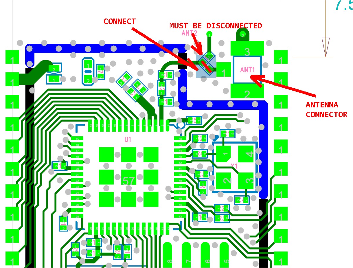
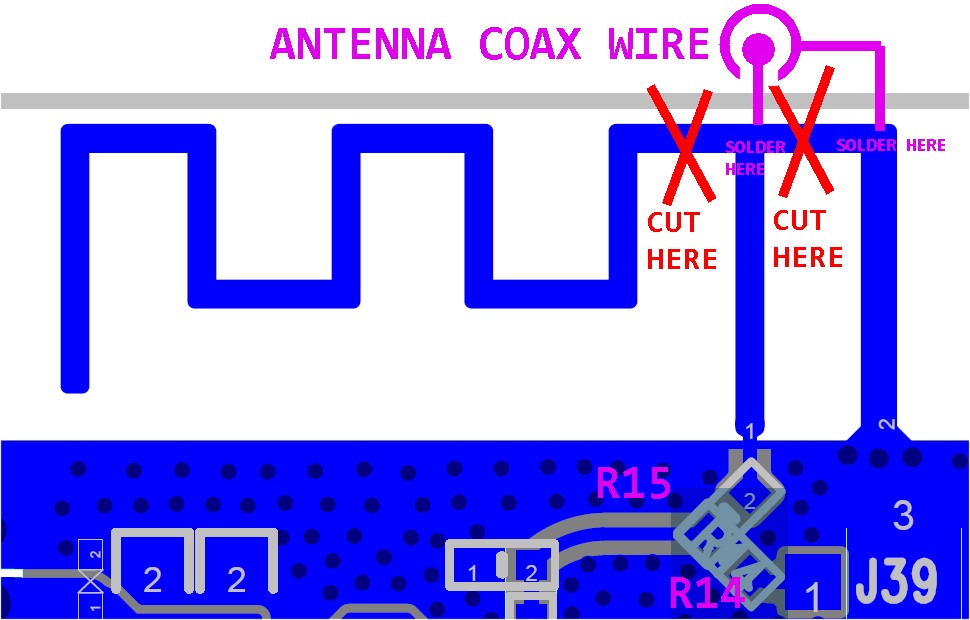
I made two experiments. First, I simply soldered an antenna to an ESP8266 copper PCB antenna output and GND with little signal strength improvement. I tired the same with an ESP32 module. Further studying the antenna part of an ESP32-S module (used by ESP32-CAM) blueprint I discovered that all the modules are internally designed with an inbuilt and an external antenna option. There are two 0 ohm resistors that connect internal (R15) and/or external antenna (R14). A standard ESP module has no antenna plug and the part of the PCB where the antenna plug may be soldered is covered with a metal cap. The design of the inbuilt PCB antenna is interesting, because it short circuits the antenna input to create a strong enough electric current that also divers the rest of PCB antenna.
However, a standard external 2,4 GHz antenna can only achieve a high performance without short circuiting the antenna output. This can be achieved by modifying the internal PCB antenna into an external antenna contacts. It suffices to cut the antenna current loop with an alpha knife to decouple antenna and GND pins. Many ESP32 have a protecting cover over the PCB antenna, so it must be scrubbed off first. The original PCB antenna now acts as an antenna output, where a 2,4 GHz antenna connecting coax wire can be soldered.
New measurements now show about 20 dBm increase in signal strength, which enables vastly increased link data transfer rate.
ESP32-CAM or ESP32-S external antenna connection
Connecting an external antenna to Ai Thinker ESP32-CAM module may greatly extend the module’s range and its digital camera picture quality. ESP32-CAM modules are based on Espressif Systems ESP32-S module which has an optional external antenna connector. But it is not enough to simply connect an external antenna.
You also need to either move 0-ohm resistor form R7 to R6 position as shown on the photo, or remove R7 and short circuit R6. This work requires a sharp eyesight and a magnification glass is recommended. A standard 1 mm soldering iron tip may be used, but it is hard move the 0-ohm resistor to R6 position with it, a mini flat screwdriver may be of help here. But you may still remove the resistor and place a short piece of wire instead of R6 0-ohm resistor, which is basically does the same. The easiest way to do this is to solder a longer piece of thin wire across both of R6 contact and then cut the wire to the length between R6 contacts. I managed to do this with ease.
Alternatively, you may short circuit R6 and leave R7 in place, but then you still have to cut the PCB antenna current loop as shown above.
Here is the antenna part of the ESP board blueprint (click the picture to enlarge it) How to solder antenna cable (click the photo to enlarge it)Switching ESP32-S module to external antenna (click the picture to enlarge it)Sign in|Recent Site Activity|Report Abuse|Print Page|Powered By Google Sites


Comments
Please log in or sign up to comment.