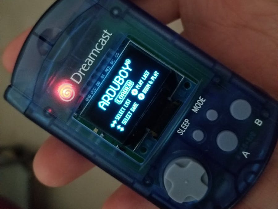
With all the really cool advances and games coming out for the Arduboy system, I though it would be really cool to fit one into a VMU. I've always loved the aesthetics of the VMU and found one for $4 with a damaged LCD at a thrift store so I thought it would neat to do something with it.
Features and PCB LayoutTo start I definitely wanted a built in Lipo battery (the original VMU chews through CR2032s and I didn't want this device to continue that legacy). So I've opted for a tiny chip I have used in the past and have a number in stock, the MAX1555. I did a little test fitting in the shell and unfortunately in order for the battery to fit I will need to cut away the coin cell battery holder plastics in the shell. The battery I chose was a tiny 220mAh battery pulled from a sandisk sansa mp3 player. The original Arduboy sports a super thin 180mAh battery so we are off to a good start.
The second major feature I wanted to add was a soft power button since the VMU has a sleep button anyway. To achieve this I opted for the MAX16054, basically a low power digital toggle switch. The output of this on/off switch goes to the enable of the 3.3V regulator that drops the lipo's ~4V down so I can safely and directly interface the main chip, a Atmega32U4, with the 0.9" SSD1306 OLED and the onboard 8MB serial flash to store hundreds of games. Finally, in relation to power, the quiescent draw of the MAX16054 is anywhere from 7-20uA so given the 220mAh battery capacity the standby time theoretically sits around 1.26-3.59 years (very rough estimate and likely only to be half that if I'm lucky). Still I though it would be a good idea to add a physical power switch (hidden under the top cap next to the usb port) to cut off the battery for long term storage.
So the first pcb/schematic design ended up looking like this:
Not pretty, and hopefully the measurements I took from the original VMU pcb with the help of my calipers are close enough for everything to fit. I managed to order the boards just in time before the Chinese new year started so in the next log I will post the results of pcb v1.0!
1st PrototypeSo I've started assembly which will go into the project video and linked when that is complete. There are a few small(ish?) errors I've made but the good news is that electrically everything works great. Last night I was able to charge the battery, flash the bootloader and load up a good 20 games or so and play for an hour before I went to sleep. Here's a quick demo:
So what are the mistakes I made this time (I like to think of them as learning experiences) due to my impatience in getting the order in before my fab house shut down for holiday? Well here's an incomplete list in no particular order:
- all drill holes are too small and cutouts on the sides near the screen are much too shallow (easy fix)
- the footprint I drew for the OLED screen has through hole pads that are also too small (easy fix)
- the power switch and micro usb port at the top are recessed into the shell and very difficult/impractical to use once the shell is screwed together (I will have the board jut out at the top to allow easier access and 3D print a part to cover the gaping hole left where the socket from the original VMU is)
- while the alignment of the buttons seems pretty good, I've noticed the tiny dpad is super sensitive making it pretty easy to hit the wrong direction while playing (I'll try modifying the button pads to support small metal snap domes to give more tactile feedback and hopefully resist mis-presses)
So for the first prototype to fix most of these issues I've had to do a bit of a bodge job to get everything to fit and work but there is at least nothing major that needs to be changed for v2.0 of the board. So I'll make the necessary changes and order another set of boards.
Fitting PCB into the VMU ShellSo I finished up shoving everything into the VMU shell and playing it for the past few days with no issues beyond those described in the last post. Here's an assembly, flashing and testing video:
PCB Rev 2, Incremental Improvements
I made a few changes based on small issues I found with the first pcb revision, namely:
- The location of the usb port on top was too inset, causing thicker cords not to plug in fully
- I wanted to expose the 6 pin ICSP header at the top so the user can easily load/change the bootloader should they wish
- A few components were shuffled around to better fit the case (this still needs some work as some parts still foul with the shell plastic supports, requiring minor trimming/cutting)
- The screw holes were too small, so they were slightly enlarged
Anyway here are the new pcbs:
Unfortunately the ~300mAh battery still requires cutting out the coin cell plastic supports in the shell, no way around that unless I were to redesign the pcb to use lithium rechargeable coin cells (at the cost of runtime).
Here's the new top port layout (including the hard power switch to conserve battery during long storage). Notice how all ports are now flush with the top of the shell, but still hidden when the cap is popped on.
Charges perfectly over micro usb.
And she runs beautifully (albeit very tiny with the 0.9" ssd1306 oled screen, but still playable).
And that's it for this revision, still need to tidy some small details up and figure out screen protection as the oled is completely exposed.


_1x_bGT19vVAby.png?auto=compress%2Cformat&w=40&h=40&fit=fillmax&bg=fff&dpr=2)

Comments
Please log in or sign up to comment.