


Hardware components | ||||||
| × | 1 | ||||
| × | 1 | ||||
 |
| × | 1 | |||
 |
| × | 1 | |||
 |
| × | 1 | |||
| × | 1 | ||||
| × | 1 | ||||
Software apps and online services | ||||||
 |
| |||||
This is simple yet very useful home security alert DIY project. I made this project because of Theft in my office. So here is the guide to build your own door security alert project to protect your home or office.
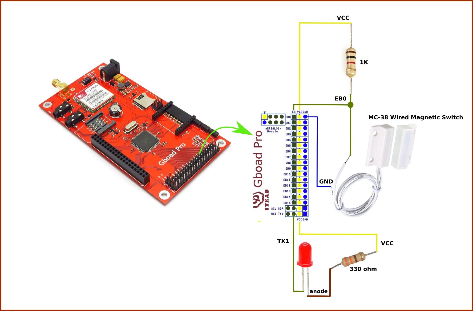
The working concept of the circuit is simple:
Case 1: When the magnets are close to each other, the circuit acts as a closed switch. Thus, the controller pin gets logic 0 (LOW)
Case 2: When the magnets are separated, the circuit acts as an open switch. Thus, the controller pin gets logic 1 (HIGH)
Follow the Arduino official link below to install Arduino IDE on your respective OS:
On Windows -> https://www.arduino.cc/en/Guide/WindowsOn Mac -> https://www.arduino.cc/en/Guide/MacOSOn Linux -> https://www.arduino.cc/en/Guide/Linux
Click Here to download library file. Extract and copy to Arduino -> libraries folder as in shown below.
Now, open Arduino IDE and you can check out sample codes for GSM GboardPro.
More details about Gboard Pro available here: https://www.itead.cc/wiki/Gboard_Pro
Step 3: ProgrammingFor uploading code, we need USB to serial converter. I have used the cp2102 connection shown in the above image.
Pin connection:
CP2102 <--------> Gboard Pro
GND <----> GND
RXD <----> RXD
TXD <----> TXD
DTR <----> DTR
also, connect the 12V power adapter to GboardPro board for power.
If you are using same CP2102 then install the driver from the link: https://www.silabs.com/products/development-tools...
Now, select proper Arduino mega board from the tool -> boards with a suitable port as shown below.
Make suitable changes mentioned in code related to your number.
char number[]="+91xxxxxxxxxx"; //Destination number
Copy below DoorSecurityProject_Code from code section in your Arduino IDE, compile and hit upload. Code is simple self-explanatory with comments. Still, if any doubt, comment below.
Step 4: Packaging and InstallationUse a suitable box to pack the system as shown in images and install on the door of your home or office.
You can even extend this project to the next level by other security sensors like a PIR motion sensor to detect human presence.
That’s it, thanks!


Comments
Please log in or sign up to comment.