Introduction:
About 65 GW of solar capacity is expected to be added globally in 2016, with Asian countries in the lead. Indian solar market appears in full bloom right now. But PhotoVoltaic systems have a potential performance problem of module soiling (dust or soot from local air pollution). It can reduce energy output significantly. Studies on module soiling show an average annual energy loss of 5% for arrays that are not periodically cleaned. Also in recent years we have seen lots of Solar Panel Theft Cases in various countries. So there is a need for smart solution to tackle those problems. So my project proposes a solution for 1) Theft prevention and 2) Maintenance Indication of solar panel using LinkIt ONE and Sensors (Dust Sensor, Current Sensor and Accelerometer). The solution provides Theft prevention for Solar Panel and also indicates the time for maintenance, thereby preventing frequent visits and save transportation cost as well as increases the usage and efficiency of Solar Panel.
1) Theft Prevention: To achieve this we use the GPS and GPRS features of LinkIt ONE Board with accelerometer. If the Panel moves or unauthorized activity occurs then there is change in axis value of accelerometer which will be detected by LinkIt ONE. It will process the data and notify the GPS location of Panel for tracking on webserver as well as on webapp. Alert action is defined on webserver like email alert or sms.
2) Maintenance Indication: To achieve this function we use Dust, Voltage and Current Sensors. So when the deposition of dust on Panel increases the efficiency start to reduce, this can be monitored by LinkIt ONE using the sensor values. It will update this data on webserver which can be viewed to know the time for maintenance of Panel.
In both cases we use GPRS feature of LinkIt ONE to send data on Ubidots webserver.
Steps for Building the prototype:
Step 1) Getting started with LinkIt One Board
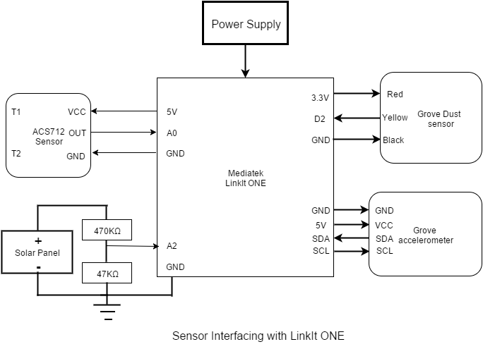
Step 2) Interfacing and Testing of Sensors with LinkIt ONE
Step 3) Setting up Ubidots Webserver for project
Step 4) Building standalone Webapp
Step 5) Final Assembly and Testing
Let’s Begin with the development of Our Prototype
Step 1) Getting started with LinkIt One Board
For this step we need LinkIt ONE board only. During testing process make sure switch position as UART, USB and SPI mode as shown in figure.
Switch needed to change only when your are required to update firmware of LinkIt ONE if you face any trouble in uploading codes to it.
Link of document which guides you through process of firmware update:
https://labs.mediatek.com/fileMedia/download/5fed7907-b2ba-4000-bcb2-016a332a49fd
Here are various links for getting started with LinkIt ONE board and setups:
https://labs.mediatek.com/site/global/developer_tools/mediatek_linkit/get-started/index.gsp
http://www.instructables.com/id/LinkIt-ONE-Getting-Started-Guide/
This guides you through the process of installing drivers and uploading codes to LinkIt ONE. Also you will find details of board.
Step 2) Interfacing and Testing of Sensors with LinkIt ONE
This videos demonstrate interfacing details of each sensor and step by step testing process.
1. Grove Acceleromter sensor interfacing:
Get Grove 3-axis accelerometer(±16g) mention in components lists
Interfacing is simple, download the accelerometer zip file from below link and extract it in libraries folder of arduino
http://www.seeedstudio.com/wiki/File:DigitalAccelerometer_ADXL345.zip
You will find demo code in example section of arduino after zip file extracted and for theft protection functionality test, use Theft_protection_accelerometer.ino code present in code section.
2.Grove Dust Sensor interfacing :
Connection is shown in video & for testing this sensor use Grove_dust_sensor.ino provided in code section.
If you need more explanation of Grove sensor refer this link
http://wiki.seeed.cc/Grove-Dust_Sensor/
3. Voltage Sensor interfacing:
Since the analog pins of LinkIt ONE is tolerant upto 5V only, so we need to use voltage divider network to bring down voltage of panel within the range of LinkIt ONE (0-5V).
So select R1=470k and R2=47k
Voltage at A2 = VINxR2/ (R1+R2)
=VIN/11
So upto 0-55V range we can measure
For making voltage divider network we have two option
1) Build simple base shield which have voltage divider network and base for current sensor module. You need some tools for this step.
Below shown is steps to make it.
2) If you don't want to go for soldering then you can use breadboard for its implementation as shown in below image
For voltage sensor test we have two code file analogVoltage_readL.ino and analogVoltage_readL_calib.ino. On testing analogVoltage_readL.ino with Arduino uno it shows proper voltage reading but with LinkIt ONE there was great difference so I have calibrated code analogVoltage_readL_calib.ino for LinkIt ONE. Both codes available in code section, check which one works for you.
4. Current sensor interfacing:
The ACS712 sensor read the current value and convert it into a relevant voltage value, The value that links the two measurements is sensitivity (you can find it on the datasheet: http://www.allegromicro.com/~/media/Files/Datasheets/ACS712-Datasheet.ashx?la=en ) which – for 5A model – has a typical value of 185mV/A.The sensor can measure positive and negative currents (range -5A…5A), and power supply is 5V for the sensor, and the middle sensing voltage is 2.5V when no current. It measure both AC and DC current.LinkIt ONE analogRead() function outputs a value between 0 (0V in input) and 1023 (5V in input) that is 0.0049V for each increment. We will use the following formula to covert the 0 ~1023 value to an ampere value.
For testing, I have used 12V supply given to DC fan (Load) whose current is measured. Code file for this test is current_sensor_test.ino
For combine testing of current and voltage you can use Current_Voltage_Read.ino file from code section.
adxl_Voltage_current_dust.ino file in code section is for combine testing of all sensors.
Step 3) Setting up Webserver for project
I am using Ubidots webserver for my project. Below is setup process for it.
Step 4) Building standalone WebApp
If you don’t want to login your webserver just to see parameters data than you can build standalone webapp. This can be open directly to visualize your webserver data, so login only when complete analysis of individual data required.
To make webapp for your webserver steps are:
1. Download index.html and location.html in one folder from code section
2. Copy the embed code of variable setup at webserver which in iframe format from dashboard as follow
3. Open index.html and location.html file in any text editor. Replace iframe section with your iframe obtained from previous step in index.html for variables and GPS location iframe in location.html as follow
4. Open index.html in browser and you are done.
Step 5) Final Assembly and Testing
Now we are ready for final assembly of project and testing. Here are steps
After complete assembly, upload final code to LinkIt ONE provided in code section Project_Code.ino file.
If you are done with uploading of final code, now here we need to change switch position of LinkIt ONE to powered it with battery.
Final Results:
Here are screen shots for the working of solar panel dual management system.
Webapp pages view
During normal operation device sends data of each sensors for monitoring of each parameters(current, voltage, dust and battery level) and LinkIt keeps on checking accelerometer. Once panel moved or unauthorized access happens then device detects it using accelerometer sensor. After this device start sending only the GPS location of panel with battery for tracking and activity is indicated using alert variable on Ubidots.
Activity or monitoring can also be viewed on webapp. Once alert is high then click on track button to trace device GPS location.
Known Issues:
1) GPS reading is not accurate as compare to our mobile phone GPS.
2) Analog read shows difference in reading. With 5V input below is test result
that is why I calibrated but still there is 0.1 to 0.3 volt difference.


Comments
Please log in or sign up to comment.