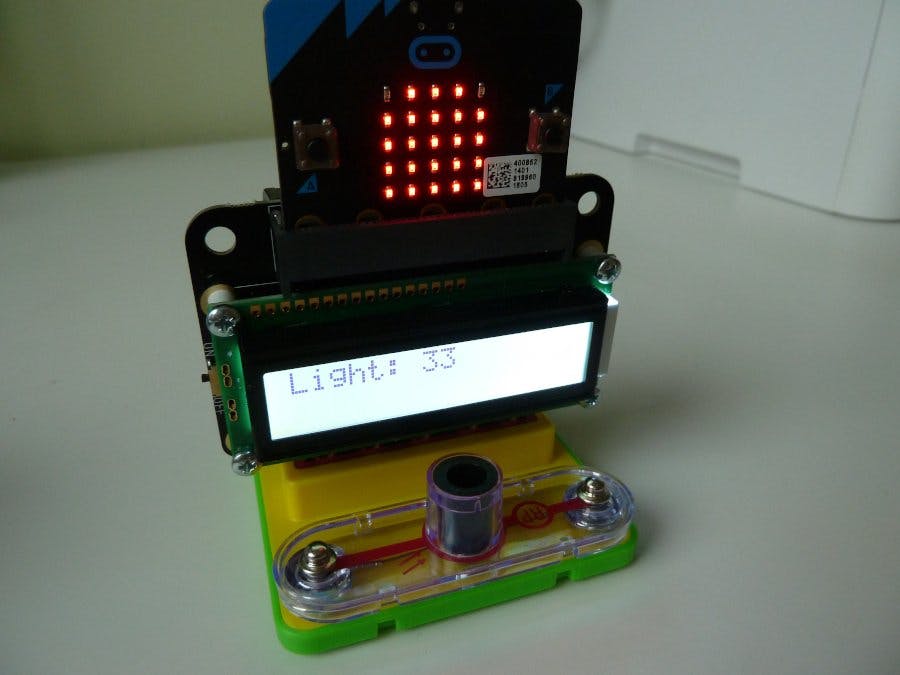
The snap:bit is an electronic component for the Snap Circuits educational electronic kit. It features a socket for connecting the BBC micro:bit. This allows the Snap Circuits to be programmatically controlled by the micro:bit.
The BBC micro:bit can estimate the amount of ambient light through the LEDs on its matrix display, but this method is not very accurate. The Snap Circuits comes with a photoresistor component that does this job much better.
This project demonstrates how to connect the Photoresistor (RP) of Snap Circuits to the micro:bit and use it as a light sensor.
We will indicate the amount of ambient light on the micro:bit LED display by plotting a vertical graph.
If you have the optional Kitronik :VIEW text32 LCD Screen, we will display the actual value of the analog input that the micro:bit reads from the photoresistor.
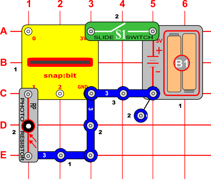
Snap Circuits diagramBuild the circuit shown in the diagram above.
CodeYou can build the code yourself in the MakeCode Editor. You will find the blocks in the following sections:
- The "set" block is under the Variables section.
- The "analog read pin" block is under the Advanced > Pins section.
- The "plot bar graph" block is under the Led section.
- The "max" block is under the Math section
- The "show string" block works only if you have the Kitronik :VIEW text32 LCD Screen. You have to install the "kitronik-viewtext32" extension under the Advanced > Extensions section. Search for "text32" if you don't see it on the list.
- The "join" block is under the Advanced > Text section.
- The "pause" block is under the Basic section.
Alternatively, open the ready project here: https://makecode.microbit.org/_67FaCC2R48z1
Once ready, download the code to your micro:bit. Then disconnect all cables from your micro:bit. Both the USB and the battery pack must be disconnected from the micro:bit.
How it works...The photoresistor (RP) is a special resistor that can be used as a light sensor. Its resistance value changes from nearly infinite in total darkness to about 1 kΩ when bright light shines directly on it.
When you close the slide switch (S1), the Battery Holder (B1) powers the snap:bit through the 3V snap and the micro:bit turns on. The "forever" loop starts, reads the analog input from pin P1 and sets the value to the "light" variable.
The brighter the environment is, the lower the value will be read from pin P1 where the photoresistor is connected. The darker it is, the greater the value will be read. In a bright environment, the reading from the photoresistor should be lower than 50. In a darker environment, the reading may reach a value of 200 or even greater.
We want to display the reading on the LED display in a way that it reflects the intensity of the ambient light, i.e. the lighter the environment is, the more LEDs will be turned on, and the darker it is, the fewer LEDs will be turned on. This is achieved by using the "plot bar graph" block.
It is important that we pass the value of max(0, 200-light) to the block because we want to display the inverted value of reading. For example:
- If the reading is 10 (bright light), the value of max(0, 200-10) = 190 will be displayed on the graph and most LEDs on the display will be turned on.
- If the reading is 250 (dark) then the value of max(0, 200-250) = 0 will be displayed on the graph and the LED display will be dark too (actually only the middle LED on the bottom row will be turned on, but this is how the "plot bar graph" block works when the value is 0).
Then the "show string" block updates the Kitronik :VIEW text32 LCD Screen (if available) to display the text "Light: <light>" on the top row of the screen.
Finally, we set a small pause to avoid constantly updating the LED and LCD screens.
This process repeats endlessly in the "forever" loop. The vertical bar on the LED display and the text on the LCD screen are adjusted in real-time as the light shining on the photoresistor changes.
If you run this project during the day, there should be a lot of light shining on the photoresistor. Its resistance value would be low and the micro:bit would read a value closer to "0" from pin P1.
Cover the photoresistor with your hand and see more LEDs alight on the micro:bit display. This happens because the resistance value of photoresistor increases due to the less light shining on it. The higher resistance causes the micro:bit to read a higher analog value from pin P1.
Can you go to a darker place? Check how the micro:bit will detect the change in the ambient light.
Minimal Photoresistor connectionJust like some other Snap Circuits components, you can connect the Photoresistor (RP) directly across the 1 and GND snaps on top of the snap:bit without any additional wires.
This minimal setup is very useful when experimenting with the code and the micro:bit is connected to the computer. Or when you have the Kitronik :VIEW text32 LCD Screen connected like we had on the cover photo of this project. In this case, the batteries of the LCD screen power the micro:bit too.


Comments
Please log in or sign up to comment.