

Hardware components | ||||||
 |
| × | 2 | |||
 |
| × | 1 | |||
 |
| × | 1 | |||
Software apps and online services | ||||||
 |
| |||||
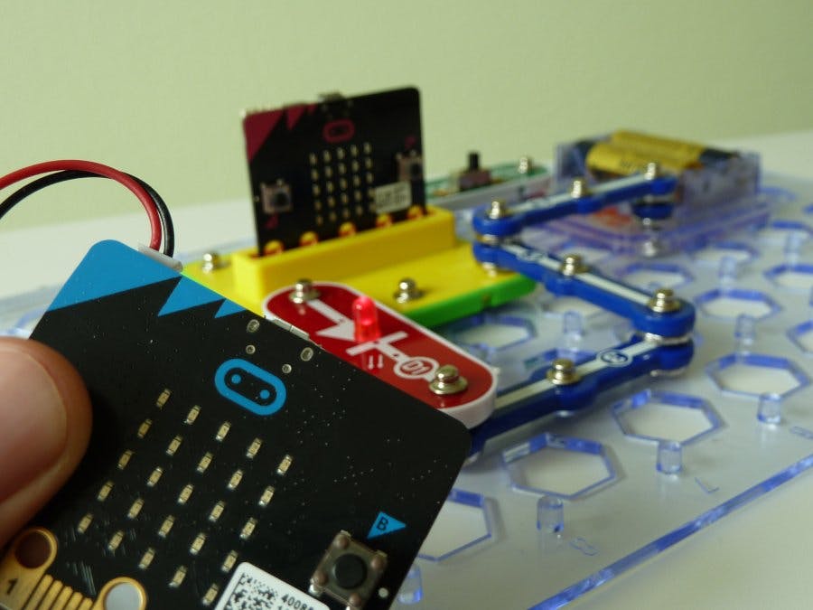
The snap:bit is an electronic component for the Snap Circuits educational electronic kit. It features a socket for connecting the BBC micro:bit. This allows the Snap Circuits to be programmatically controlled by the micro:bit.
This project demonstrates how to control remotely the Red LED (D1) component from Snap Circuits. It uses two BBC micro:bit - a sender and a receiver.
Pressing the buttons on the sender will transmit a radio signal to the receiver. The receiver is plugged in the snap:bit and turns the connected LED on and off based on the received radio message.
This project is similar to Connect Snap Circuits' LED to Micro:bit. It does the same but uses an additional micro:bit as a remote control.
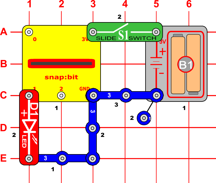
Snap Circuits diagramBuild the circuit shown in the diagram above.
CodeTo keep things simple, the code for this project is the same for both the sender and the receiver micro:bit.
When started they initialize their radio. Pressing either button A or button B sends the number "1" or "0" respectively to the other micro:bit. When the other micro:bit receives the number, it writes it to pin P1.
You can build the code yourself in the MakeCode Editor. You will find the blocks in the following sections:
- The "radio set group" and "on radio received" blocks are under the Radio section.
- The "digital write pin" block is under the Advanced > Pins section.
Alternatively, open the ready project here: https://makecode.microbit.org/_gds4XLD4q35T
Once ready, download the code to both micro:bits. Then disconnect all cables from one of the micro:bits and plug it in the snap:bit - this is the receiver. Leave the other micro:bit connected to the USB or to a battery pack - this is the sender.
How it works...When you close the slide switch (S1), the Battery Holder (B1) powers the snap:bit through the 3V snap and the receiver micro:bit turns on. The “on start” event triggers and the micro:bit initializes the radio and tunes it to group 1.
Powering the sender micro:bit either via a battery pack or through USB turns it on. Its own “on start” event triggers and this micro:bit also initializes the radio and tunes it to group 1.
Now both micro:bits a tuned to the same radio group and they can communicate to each other.
Press button A on the sender micro:bit. The "on button A pressed" event triggers. It sends the number "1" through the radio to the other micro:bit.
The receiver micro:bit receives the radio message. The "on radio received" event triggers and the number sent by the first micro:bit is set to the "receivedNumber" variable. The receiver micro:bit now writes this number to pin P1 where the LED of Snap Circuits is connected. Since the number is "1", the LED turns on.
Press button B. The sender micro:bit now sends the number "0" to the receiver, which writes it to pin P1. This turns the LED off.


Comments
Please log in or sign up to comment.