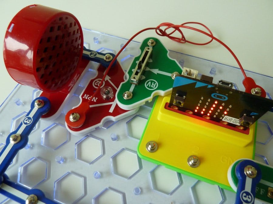
The snap:bit is an electronic component for the Snap Circuits educational electronic kit. It features a socket for connecting the BBC micro:bit and allows the micro:bit to programmatically control Snap Circuits.
This project demonstrates how to amplify the sound coming from the BBC micro:bit before playing it through the 8Ω Speaker (SP) of Snap Circuits.
It is similar to the Connect Speaker With Amplifier to Micro:bit project where we used the Amplifier IC (U4) part to amplify the sound and hear it loud and clear. In this project, instead of the Amplifier IC, we will use the NPN Transistor (Q2) to do the same. We will also use the Adjustable Resistor (RV) to control the volume of the sound.
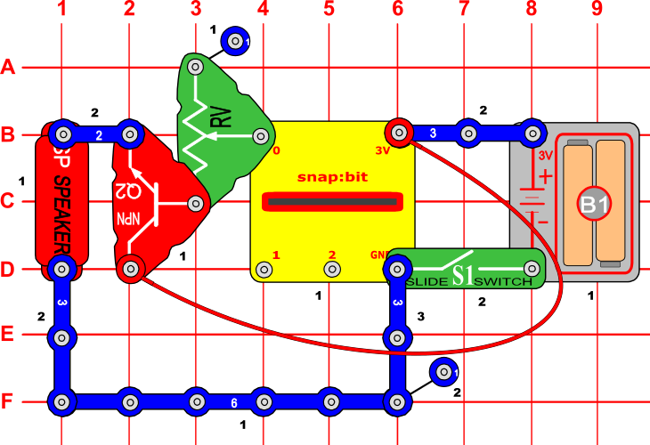
Snap Circuits diagramBuild the circuit shown in the diagram above.
CodeYou can build the code yourself in the MakeCode Editor.
Alternatively, open the ready project here: https://makecode.microbit.org/_JtEPxq7xxFCg
The "set built-in speaker" block is required only for the BBC micro:bit V2. The new version of the micro:bit comes with a built-in speaker. You must turn it off to hear the sound through Snap Circuits' speaker.
Once ready, download the code to your micro:bit. Then disconnect all cables from your micro:bit. Both the USB and the battery pack must be disconnected from the micro:bit.
How it worksThe micro:bit plays music through pin P0. So the Speaker (SP) snaps must be connected across snap 0 and either the 3V or GND snap of the snap:bit. However, in the Connect Speaker to Micro:bit project, we have seen that connecting the speaker directly to pin P0 of the micro:bit leads to a low sound level. The reason for this is the low current coming out from pin P0. To hear the sound loud and clear, we use the NPN Transistor (Q2) to amplify it.
When you close the slide switch (S1), the Battery Holder (B1) powers the snap:bit through the 3V snap and the NPN Transistor (Q2) in parallel. The micro:bit turns on. The “on start” event triggers, and the micro:bit plays the melody.
The micro:bit modulates the sound like a current through snap 0, which is connected to the NPN Transistor base through the Adjustable Resistor (RV).
The small amount of current flowing through the transistor base triggers a larger amount of current to travel from the collector to the emitter. The transistor's collector is connected to the positive terminal of the Battery Holder (B1) through the Red Jumper Wire. The emitter is connected to the Speaker (SP), which is connected to the GND snap and the Battery Holder's negative terminal.
The NPN Transistor quickly switches the amount of current traveling from the collector to the emitter based on the current supply to the base. This quick switching allows the current flowing to the speaker to follow the same pattern of the modulated electric signal supplied to the base of the emitter from the micro:bit. This way, the NPN Transistor amplifies the audio signal coming from the micro:bit, so we can hear it loud and clear through the Speaker.
The Adjustable Resistor (RV) is optional. It controls the amount of current supplied to the base of the NPN Transistor. The larger the current supplied to the base is, the larger current will flow from the collector to the emitter. This way, the Adjustable Resistor acts as a volume control. Slide it up and down to see how this affects the sound volume.


Comments
Please log in or sign up to comment.