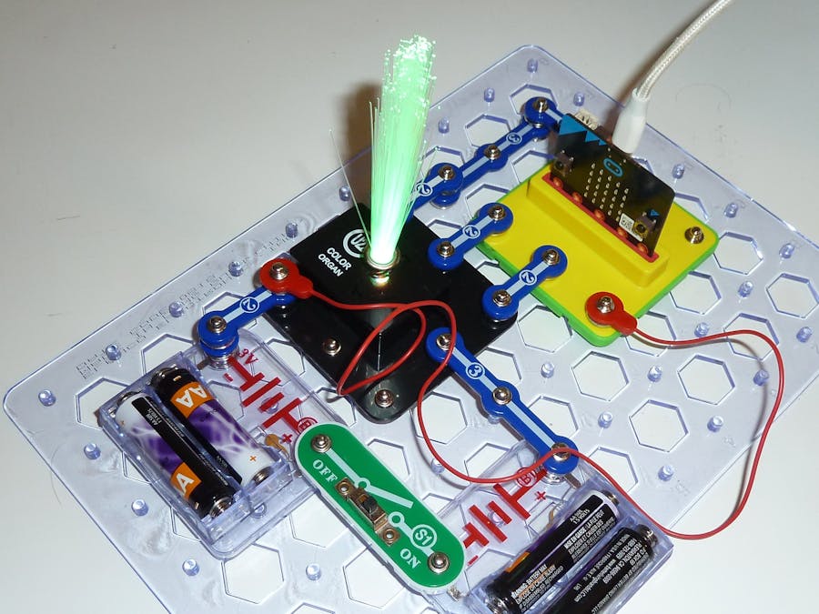
The snap:bit is an electronic component for the Snap Circuits educational electronic kit. It features a socket for connecting the BBC micro:bit. This allows the Snap Circuits to be programmatically controlled by the micro:bit.
This project demonstrates how to connect the Color Organ (U22) of Snap Circuits to the snap:bit and control its color with the BBC micro:bit.
The Color Organ (U22) is one of the complex parts of Snap Circuits. It integrates an RGB LED, which is actually 3 LEDs (Red, Green, and Blue) in the same package. Each of the three LEDs can be programmed to light with a different intensity, which makes the RGB LED to produce a great variety of colors.
In this project, we will program the color to show a new random color every second.
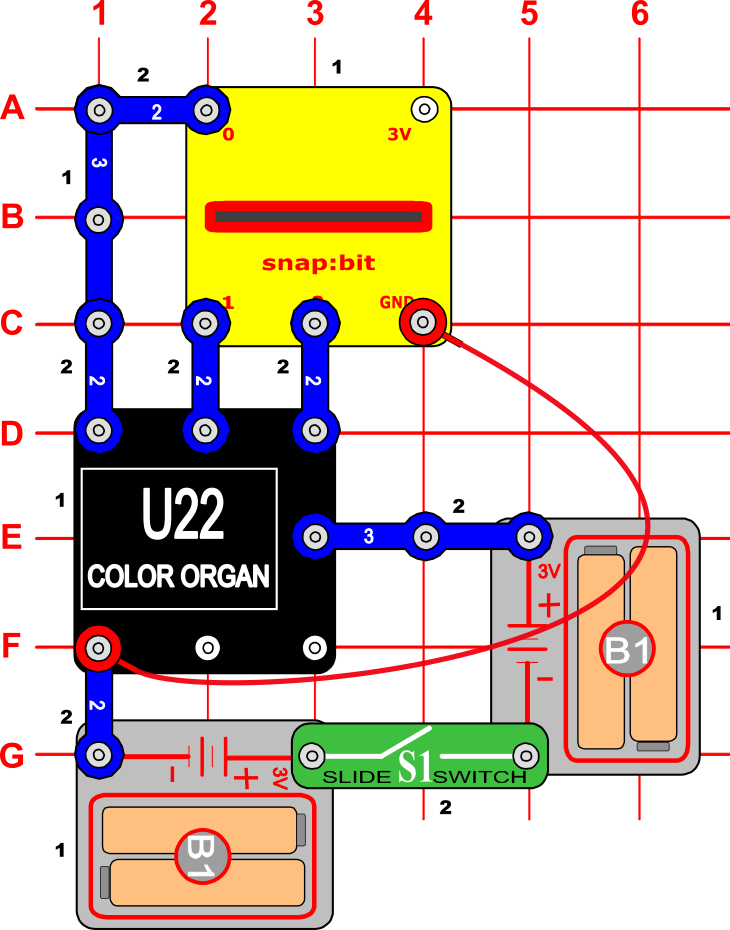
Snap Circuits diagramBuild the circuit shown in the diagram above.
Note that the Color Organ must be connected to a 6V power source to operate properly. This is the reason we use two Battery Holders (B1) connected in series.
At the same time, the BBC micro:bit must be connected to a 3V power source. Powering the micro:bit with a higher voltage will damage it.
To avoid accidents with powering the micro:bit with a high voltage, we power it with a USB cable instead of from the battery holders of Snap Circuits. This also supplies a stable 3.3V current from the micro:bit pins to the color organ, which is important for proper operation of the RGB LED.
CodeYou can build the code yourself in the MakeCode Editor. You will find the "analog write pin" block under the Advanced > Pins section, and the "pick random" block under the Math section.
Alternatively, open the ready project here: https://makecode.microbit.org/_9WiivE518KtJ
Once ready, download the code to your micro:bit.
How it works...Close the Slide Switch (S1) that is between the two Battery Holders (B1). This closes the circuit between the (+) and (-) snap buttons of the Color Organ (U22), which turns it on.
As the micro:bit is powered from the USB cable, it already is continuously going through the "forever" cycle of the program. On each iteration, the micro:bit sends an analog signal of random intensity to each of the P0, P1, and P2 pins.
The P0 pin of the micro:bit is connected to the R snap button of the color organ. The P1 pin - to the G snap button, and the P2 pin - to the B snap button, respectively.
This way, the random intensity of the signals through the P0, P1, and P2 pins of the micro:bit makes the red, green and blue LEDs in the color organ to light with a corresponding intensity, producing a beautiful random color.
This process repeats every second and so we see a different color every second.


Comments
Please log in or sign up to comment.