Instructions
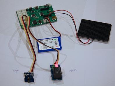
First, plug the Switch into the D2/D3 pin in the always on row.
Then, plug the Relay into the D4/D5 pin in the always on row.
Next, plug the 0.5W solar panel and the 1A LiPo battery into the respective sockets (see http://www.sodaq.net/#!getting-started/c21ma for a board diagram).
Turn on the SODAQ board, compile and upload the following sketch from the arduino IDE onto the SODAQ Board, and then unplug the USB cable from the computer when it is working.
You should see the light on the relay turning on when you switch to HIGH on the Grove switch, and turning off when you switch to LOW.
Code
Note
The relay in this example does not serve any real purpose, but if an electronic device such as a coffee-machine were connected to its screw terminal, it would be very useful.


Comments
Please log in or sign up to comment.