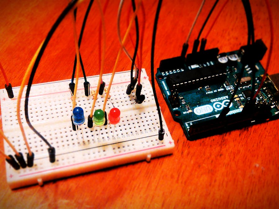
In this tutorial I'll combine everything I've been telling about so far (Part 1, Part 2) adding additional knowledge about analog output with LabVIEW. As a result you will be able to create simple temperature sensor with indicators according to read temperature.
Board SchematicsAs previously let me start with schemat design. In this design beside temperature sensor I'll use 3 LED (in my case red, green and blue). It doesn't matter which temperature sensor you have as long as it has analog output.
Idea here is to use red and blue LED as a binary indicators, while green LED as an analog output where light intensity will be corresponding to the temperature value from sensor.
Another way of reading temperatureLast time I showed you how to read analog value using multiple blocks. However, it is not the only way to achieve this goal. LabVIEW has a lot of VIs as you might find out already. Some of them may seem very simple (like Digital Read or Digital Write) and some are a little bit more advanced (like Initialize). Truth is, that almost all of them at some point are designed from other blocks, and what you see are SubVIs.
Take from MakerHub->LINX->Sensors->Temp block TMP3x. This is single block capable of doing exactly the same thing we've been designing in the last tutorial (it is important to remember, that the output value is only in C).
If you are using another temperature sensor there is possibility you will not find it as a block. Because the list of temperature sensor blocks is very small you can always use old approach described in part 2 of this series.
To open and see how SubVI is build you can double click on it with left mouse button, or click it with right mouse button and go to Open Front Panel. What you'll find is VI with Front Panel and Block Diagram. Don't get fooled by strange symbols on Block Diagram. Those are normal elements, but displayed without icon. To display them right click on the component and select View As Icon. Thanks to this SubVI our diagram will be much cleaner.
Writing to analog outputNow when we took care of reading analog input values it's time to write them as well. Even though LINX has special blocks for analog writing in Analog group, they will be no use in this project. The reason for that is because LINX can work not only with Arduino, so even if this specific board doesn't support it, doesn't mean that other aren't. Instead there you need to use PWM to output analog values.
This approach is also correct with Arduino's design as you probably know already. In MakerHub->LINX->Peripherals->PWM is only one block - Set Duty Cycle and we will use it here In our case in will be only one chanel, but it can also work with multiple channels (which is useful for example when working with RGB LED). In my example I amusing chanel number 6.
Remember to use correct digital outputs on Arduino. The PWMs are marked with ~.
As an input value I am using normalized reading from temperature sensor. I decided to have maximum value equal 20 C and minimum equal 10 C. All calculations are done inside Formula Node.
Ready applicationMy finished Block Diagram can be seen below.
As you can see it is not very different from the last one. Here I even used previous project as a base for this one.
I only added two additional Digital Write blocks for red and blue LED as well as simple comparison where I am checking my condition:
if temperature < 10
   turn on blue LED
if temperature > 20
   turn on red LED
Because there is no possibility that both conditions will be true I didn't add any else case.
Now you can test how your temperature indicator is working.
What's nextIn future tutorials we will be covering more and more complex blocks since right now you can create quite complex designs with just few simple blocks. This, together with its modular architecture, are great things about LabVIEW and system prototyping with it.


_ztBMuBhMHo.jpg?auto=compress%2Cformat&w=48&h=48&fit=fill&bg=ffffff)


Comments
Please log in or sign up to comment.