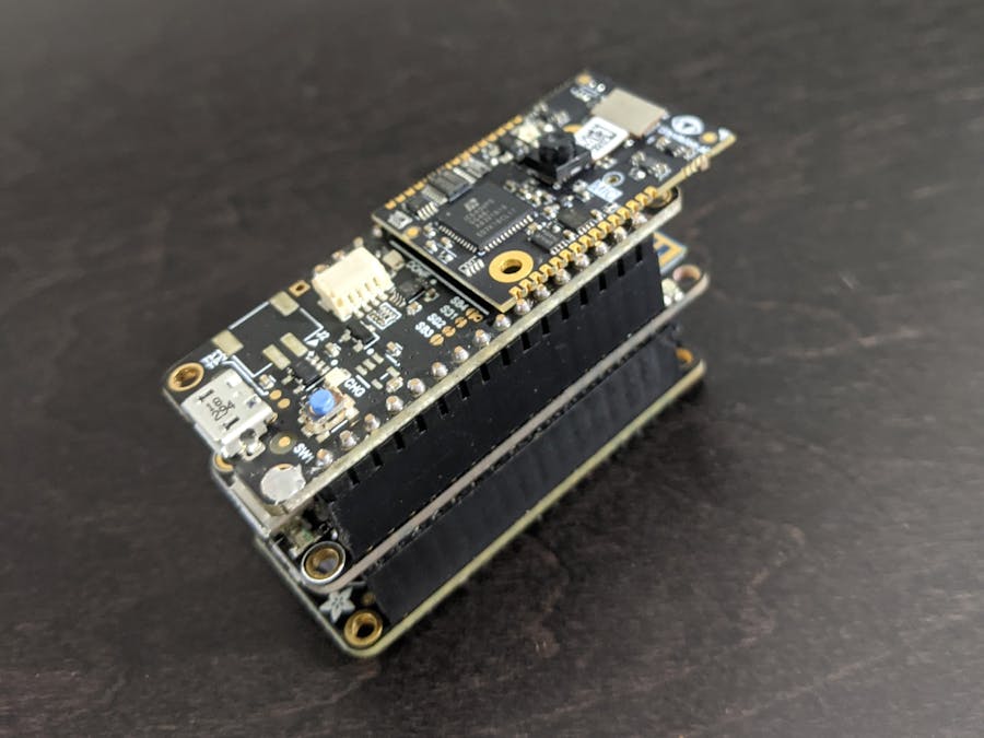
I recently posted some of the work I was doing on twitter and I got an e-mail from someone I knew that said so what, what's it good for? That's a great question, so let's start there. The camera module in this project is inexpensive (under $10) and low-power, but also low-resolution (320x320), and not exactly worthy of capturing those memorable moments of your life. However, it is great for things like doing computer vision in a battery-powered device. In particular, I'm interested in using it with convolutional neural networks (CNNs), and for that, we need data! Even if I'm going to train my CNN on public data, I will typically fine-tune it with some data specifically from the device, or at the very least, use images from the target device for testing.
PlanningThe Vision FPGA SoM is the target platform for my applications. It's small and includes an FPGA from Lattice Semiconductor as well as a low-power camera module from HiMax Imaging. There is however, no mass storage. In order to collect images, I will need a board with an SD card and microcontroller to transfer images to the card. Fortunately, tinyVision.ai offers an Adafruit Feather-compatible board for the SoM, so it can be easily used with a number Feather microcontrollers and FeatherWings.
I happened to have a Feather M0 WiFi and an Adalogger FeatherWing (NOTE: There is a Feather that includes both an M0 microcontroller and an SD card which would be a lot more convenient, but was out-of-stock at the time of this build). Since I would be combining the Feather M0 with two separate Wings (Adalogger and SoM), the next step is to check for pin conflicts.
CompatibilityThe Vision FPGA SoM is a module that mounts onto a Feather pin-compatible board. So in the end I have a four board stack! Since the three main boards are sharing pins, let's check the pinouts for compatibility.
The only pins used by the Adalogger are for the I2C interface (real-time clock, not used in this project) and the SPI (SD card). The common pins of the I2C and SPI interfaces are meant to be shared by multiple slaves so that is not usually a problem. Both boards have a pull-up register on the I2C data pin, but that seems okay in this case. However, SPI also requires a separate slave-specific chip select pin which is not standardized; it can be any GPIO. In this case, the SD card chip select is using pin GPIO 10 which unfortunately is tied to reseton the SoM board. That obviously won't do. It's an easy fix, though; I just cut the pin off the SoM board header to leave it unconnected from Feather's GPIO 10 pin.
The BuildThe first step is to solder stacking headers like these onto the Feather M0 board.
These headers allow you to attach two boards to the M0, one below and one above. I soldered female headers onto the Adalogger board to stack below, and male headers to the SoM board to stack above. Just make sure to solder the headers on the opposite side of the vision module connector so the camera mounts on the outside of the stack.
Once all the headers have been soldered on, it's simply a matter of pushing the boards together and attaching the vision module.
FPGA DesignFor those who might be unfamiliar with FPGAs they are essentially programmable hardware chips. The following diagram depicts the hardware components required to interface the camera module with the MCU.
- I2C Master - configures the camera settings at power up
- Image Capture - reads pixels from the camera sensor to memory
- SPI Slave - interface to the read pixels from MCU
A pre-built FPGA image implementing these components is provided in the attached code repository. Please see the README for programming instructions.
Arduino SketchThe Adafruit Feather platform is supported by the Arduino IDE. The Adafruit website has detail instructions for using the IDE with the Feather M0, see: Arduino IDE Setup
The sd_logger sketch is provide in the attached code repository. It does not require any configuration; just load it into the IDE and upload the sketch to the Feather M0.
Once you've programmed the FPGA on the Vision FPGA SoM and uploaded the sd_logger sketch to the Feather M0, you are ready to go. On power up, the sketch will search for the first unused filename and start capturing images after about 10 seconds. By default, it will capture 1 image per second. The RGB light on the SoM is initially blue, but will change colors every time it captures an image so you can tell if it is working... and if it stops working.
The images are written to the card in PGM format with sequentially numbered filenames CAMnnnn.PGM. The images are captured in the raw format of the image sensor (for the curious, it is a Bayer filter image). I've provided a simple Python image conversion utility to convert those to RGB images.
Install the utility with pip as follows:
python -m pip install sxlogicYou can then convert all the files on your SD card from your computer with something like following:
python -m sxlogic.iconvert --debayer --glob F:\*.*where F: here is the SD card path.
This converts to TIFF format by default and saves to the current directory. TIFF is the default because it is a lossless format. Try the -h option for more options.
Here's the first thing I did with my image logger:
Yep, that's the image logger strapped to the side of my drone with rubber bands! My first flights were pretty catastrophic as I was having some issues with GPS accuracy and my property is fraught with danger for a drone.
Here are a couple images from the drone I captured on later flights at some safer flying locations.


Comments
Please log in or sign up to comment.