The reasoning behind this post:
I wanted to be able to control a 12 volt fan or other apparatus from a Raspberry Pi and was not sure how to do this. I do not have an electrical engineering background. In college, many years ago, I took a course on assembly and some physics classes, but even with this experience, I did not really know where to start. So I started researching and hacking.
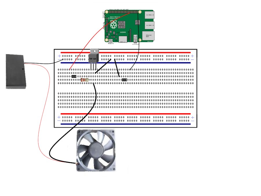
Bread Board Diagram
Requirements for Project:
Hardware Requirements:
* Raspberry Pi 2 (1x)
* Bread Board (1x)
* 18 volt AA battery Pack (1x)
* Blue tooth keyboard (1x)
* 3.5 inch LCD Screen (1x)
* TIP 120 Transistor (1x)
* 30 volt diode (2x)
* 1 Kilo Ohm Resistor (1x)
* 12 volt Fan (1x)
* Alligator Wire Clips (2x)
Software Requirements:
* Windows 10
* Visual Studio 2015 Professional
Wiring it up:
The Battery Pack is connect to the fan that is then connected to the collector of the transistor and the emitter of the transistor is attached to a common ground.
The Raspberry PIs 5th GPIO pin is attached up to a diode, which is then connected to a resistor that is connected to the base of the transistor. If the 5th GPIO pin transmits a positive current the fan turns on.
Connecting the Transistor:
The first thing, I found out was I needed a transistor. I had heard of transistor radios, but did not really understand what they were, nor how to use them.... So I researched a little more and found out that a transistor is a switch that can be turned on when current is applied. A popular type of transistor that can do this is called an NPN (Negative Positive Negative) transistor, below is a picture of the circuit diagram for this type of transistor.
The B or Base is the application that applies a small current to turn on a larger one, the collector is for the larger current. For a tip 120 transistor this can be up 120 volts. Then finally there is the emitter which needs to be connected to a common ground. Yes, the Raspberry Pi and the fan must have the same ground… this would be intuitive to someone with background in circuitry but to me, the Apprentice to the Apprentice of the electrical engineer not so much.
So the base pin of the transistor will be connected to the Raspberry Pi. The ground of the fan will be connected to the collector of the transistor and emitter of the transistor will be connected to a common ground for both the fan and the Raspberry Pi.
Connecting the Diodes
Warning: Make sure to use diodes when using transistors or the Raspberry Pi will be short lived.
Next part of the circuitry is using a diode. A diode is a one-way street for electrons, when using transistors we need to use diodes to block reverse current from coming back from the high voltage appliance/fan back to our controller, in this case a Raspberry Pi. If a 12 volt current was applied to the Raspberry Pi, it would short it out.
The white line on the diode determines which way the current will flow. The white line is for the negative current, the current for the above diode will only flow from left to right.
Battery Pack:
Changing the battery back to output 12 volts instead of 18.
If all the batteries are inserted into the battery pack it will output close to 18 volts, The fan that is being used, is designed to run on 12 volts. To meet the requirements of the fan, two of the batteries were remove and replaced with two bread board wires. Once this was implemented, the battery packed outputted 12 volts of current.
Source code:
All the Source Code for this project can be found on
https://github.com/StuartSmith/Rasberry-Pi-Fan-Control
Project in action


Comments
Please log in or sign up to comment.