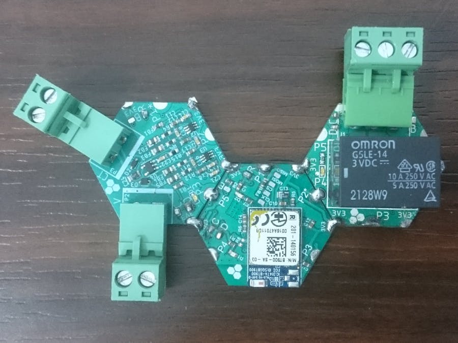
The goal of this project is to build a small system that allows you to monitor any electrical device, measure both current and voltage ( AC ), control it remotely (ON / OFF) and finally protect it from overload (all with your smartphone).
The steps are quite simple: first, we develop an Android app that sends and receives data via Bluetooth. Then we use the Hexabitz H2AR3 module, which gives us the current and voltage measurements that can then be sent to your phone via the H23R0x Bluetooth module. Finally, we need the H0FRxx relay module to turn our device on and off.
So let us go through the app with MIT app inventor
Here is a picture of the designed screen
Now we go to the block area and here is the part for connecting to Bluetooth and sending the values that we will use to turn our device on and off
here is the part for receiving the data
and here we can record the current to the changes in the curve
Before we begin, we need to load the firmwares of the three modules and open them on STM32CubeIDE. Now let us go to the modules where we need to set the topology file.
First note that this file must be the same in each module.
After that, we should give each module a ID:
H2AR3x : 1
H23R0x : 2
H0FRxx : 3
Navigate to the properties of each element and give them the ID
Now go to the user file in H2AR3 and double click on main.c and write the code. First we need to add the variables we want to share with other modules
then we take samples of the voltages and calculate their RMS value and send it to the Bluetooth module
after that we take samples of the current, calculate its RMS value and send it to the Bluetooth module
In the Bluetooth module we need to set the Bluetooth detectability, add the same common variables and make the module ready to receive data.
Here we send the date to the app in the same way we created the app
Finally, we turn the device on or off depending on what we are sending and how high the value of the current


Comments
Please log in or sign up to comment.