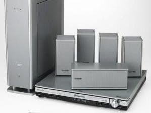
I have recently acquired a Panasonic SA-HT700 "DVD home theater sound system" from my aunt. I cannot get it to turn on -the first reason is that the main board is not getting the standby power from the sub\amp\psu, I have already checked the continuity of the cable, and I have confirmed its 6V is alive really about 5.4 in (fig1).
I also put my own separate supply into the main board that is the same voltage (fig2), standby led lights (fig3), IR in works, power button does also but with no response from anything (I found 2 wires to the psu 1 that is pulled up ("sync") and one pulled down ("h_mute") but none that change state when the power button is pressed) and the uc does work 21.7mA with the led board in (fig4) and 20.5mA not in.
After I spent at least a half an hour clipping, measuring, and fitting pieces of twisty tie (just the metal wire) into the ribbon cable, I powered it up and it talks to me (says hello, goodbye, and wait) but the fan doesn't turn on, it doesn't properly load a disk (though it is still mostly taken apart) it does a few things like the volume, and the dolby sound effects and equalizer, I haven't gotten sound to play because it wont go to any inputs (I also haven't hooked it up to a screen yet so maybe it puts it on the OSD).Discussion on Hackaday.
Update
update since then is the youtube video which i had disbanded the whole main processor and just hotwired the amp to take raw audio from my pc.
Update 2016
due to a few comments on the youtube video and here I decided to give another update, first is that I actually soldered some RCA inputs together, I used some colored solid core wire to make it half color coded, also made sure the RCA input panel had a mono/stereo switch, which will connect the front L/R to the surround L/R when there isnt a RCA cable plugged in (even though as you can see I am not using the surround speakers it adds functionality if I ever decide to use them)
next is the pinout card I had made a long time ago, I just scanned it in and highlighted things in paint, hopefully that clears up the pinout and how to hook it up to things, there is labeling of the connector on the PCB of the DVD player if you want to see some of the other pins.
one more note (as mentioned on the youtube comments) is that it has some line that is basically for tamper protection, that travels from the standby board all the way to the front display panel, it will not let the amp turn on if it isnt connected, so I just removed the transistor that it uses. it will be one of the two little ones on the standby board (Q519 or Q515) I believe it is Q519, that one has its collector to Q515's base and is always on thus pulling the base low, not letting it turn on and engage the relay. so I just desoldered the collector of that one so that it will not interfere with the one that engages the relay. (follow the relay traces it will be hard to miss).
Photos


Comments
Please log in or sign up to comment.