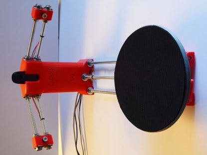
Hello guys,I am a student. I am 13 years old. This is a beautiful project to fight with Corona virus. We can make a mask in 3d printer through scanning it.This is a ciclop desktop 3d laser scanner. If you can't draw in fashion 360 or tinkercad to make things you can scan that thing with this machine and can make things easily. This works very much better. It is giving the image to computer.
The Ciclop 3D scanner allows any object of a suitable size to be scanned in three dimensions ultimately resulting in a model that after post processing can be edited, manipulated and reproduced using a 3D printer.
The object of choice is placed on a rotating platform. As the object is rotated two line lasers illuminate the object from two different angles. A camera then scans the illuminated object at each rotational position. The data from the camera is then used to build a 3D point cloud of the object.
The Ciclop scanner is constructed from the following basic building blocks:
- A series of plastic components which can be produced using a domestic 3D printer
- A series of threaded connecting rods which hold the plastic parts in position
- A microprocessor control system & firmware used to locally control the platform motor & lasers
- A good quality camera used to capture the lined scanned data
- A PC based software application used to perform calibration, invoke/control scanning and assemble the result.
Now I will show how I made it in step by step:
Step 1: The Ciclop Plastic Component Parts (Lulzbot TAZ5 Printed Using HIPS)Shown above are most of the Ciclop plastic component parts, all these components were printed on my 3D printer.
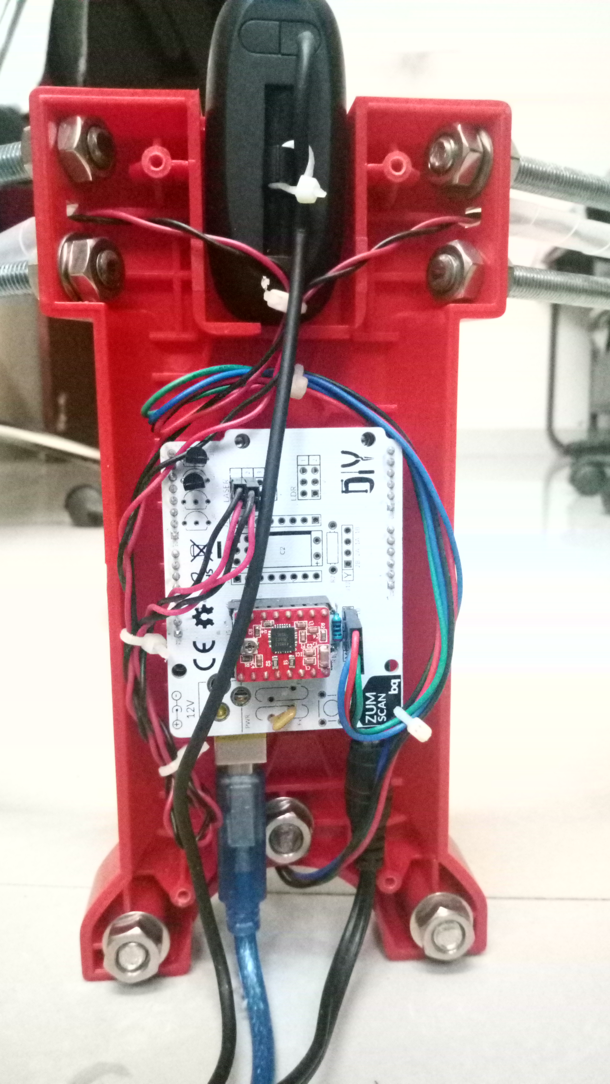
Step 2: Ciclop Framework Excluding the Motor and PlatformThe on-board motor and laser control systems is based around an Arduino UNO ATmega328P control board.
The Arduino control board is based around the ATmega328P microprocessor. The board has a simple linear power supply, a clock source for the micro, a reset button and a few leds. The idea behind the Arduino system is that you take you basic control board and then plug what is termed a shield on top. The shield is an application specific hardware board that acts as an interface between the microprocessor and whatever it is you want to control. This is a simple but very powerful system.
However, for the Ciclop the shield is a more traditional piggy back interface board. The Ciclop shield provides the hardware interface control for the bipolar stepper motor and also for the line laser control. In the case of the Ciclop shield the integration is taken one step further and a stand alone bipolar stepper motor driver module is used as these modules are used extensively in the 3D printer and home CNC market and are very inexpensive.
Step 12: Downloading the Firmware to the Arduino PlatformIn this step we will go over the process of downloading or programming the Arduino platform with the firmware.
Firmware in this context is essentially the code that runs on the Arduino ATmega328P microprocessor. The board is supplied already programmed up with the bootloader so all that is necessary is to use the Arduino Integrated Design Environment or IDE to program the board with the Ciclop firmware.
The process is as follows :
- Install the Arduino IDE after downloading from the internet
https://www.arduino.cc/en/Main/Software
- Download the latest version of the firmware, you need the horus-fw.ino sketch file
https://github.com/bqlabs/horus-fw ( I have mentioned in code section).
- Download & install the CH340G driver if you have a clone version of the Arduino board. I will elaborate slightly on this point. Authentic (non clone) Arduino control boards are fitted exclusively (as far as I am aware) with FTDI USB to serial interface devices and therefore require the appropriate FTDI software driver. In my experience once this driver is installed the board appears as a COM port and everything else operates as expected.
http://www.arduined.eu/ch340g-converter-windows-7-driver-download/
- Connect the IDE to the board via the appropriate COM port (look in the Windows device driver list to determine the correct COM port) (see screen shot)
- Select the board type (see screen shot in below steps)
- Select the programmer (see screen shot in below steps)
- Load the firmware sketch (see screen shot in below steps)
- Upload the sketch to the board
One thing that is worth trying if you are new to all this Arduino business is to up load an example sketch first just to give you the confidence that everything is working correctly. Under the IDE file menu there are a bunch of example sketches - one of which is simply called blink. This sketch once uploaded just flashes an LED on the Arduino UNO board. So you don't need the Ciclop shield fitted at this stage just upload blink and sanity check that the board LED is flashing. Once happy you can go onto load up the Ciclop sketch and program the board. The entire programming process for the Ciclop firmware takes just a few seconds.
Step 13: The Camera Connection and DriverThe camera used is a Logitech C270 HD webcam, sourced from eBay. Once you have your camera you need to install the camera driver.
I downloaded the driver from here :
http://support.logitech.com/en_ca/product/hd-webcam-c270
The camera simply slots snuggly into the top of the camera holder. The USB cable runs down through the camera holder and out of the base.
Step 14: Using the Arduino IDE to Select the COM PortNote the COM port in MY case was COM12. However, for you it may (probably will be) different. Under the Windows control panel open the device manager and check which COM port has been allocated.
Step 15: Using the Arduino IDE to Select the Board TypeOnce the firmware has been successfully programmed you can plug the laser/motor control shield onto the Arduino board - the controller is now ready for integration into the Ciclop scanner.
Step 18: The Motor ConnectionI think it is worth just going over the motor connection to the laser/motor control shield. I bought my motor from eBay and it was supplied with a header connection on the side and a plug with about 1m of cable - very nice. However, it may not be obvious how the four connections of the motor connect to the motor controller. I do quite a bit of work with stepper motors and it never ceases to amaze me how much misinformation there is on the internet regarding their connections. There are two main types of stepper motor Unipolar and Bipolar - this particular motor is a Bipolar type with four wires. Essentially inside the motor are two coils with two wires connected to each coil - hence a four wire interface.
The laser/motor control shield has a four pin header labelled 2B 2A 1A 1B
Pins 1A & 1B connect to one of the motor coils and 2A & 2B connect to the second motor coil.
Looking at the attached image for the particular motor I have the connections are as follows :
1A - Black
1B - Green
2A - Red
2B - Blue
This connection ensures the motor runs correctly and also rotates in the correct direction.
Step 19: The LasersThe lasers used in the project were 5mW focusable line lasers, again sourced from eBay. Each laser has a rotatable diffraction lens mounted on the front which projects a laser line and by rotating allows the laser line to be focused.
The laser holder plastic parts as printed were obviously intended for a laser with a smaller diameter body and so my lasers didn't fit. I could have imported the laser holder model and modified it and then re-printed ..... it was late by that stage so I just drilled out the plastic to 12mm and popped the lasers inside.
I extended the fly leads to each laser with spare red/black wire that was left over after cutting the motor lead to length. All leads were soldered and then made secure with a heat shrinkable covering.
The two lasers connect to the laser/motor control shield as follows :
Left laser connection port 1
Right laser connection port 2
The red lead connects to the inner most pin closest to the motor controller, the black lead connects to the outer most pin closest to the board edge.
Here is a link to the lasers I used:
http://www.seeedstudio.com/document/HLM1230.pdf
Step 20: Horus Application Software and DocumentationThe PC/Linux Horus application software can be found here :
http://horus.readthedocs.io/en/release-0.2/
I didn't see much point in explaining the software operation in detail when all the documentation has already been done so well.
In order to get good results I would suggest reading all the documentation rather than just diving in. There is not that much to read and after ten minutes you will be better equipt to get a good result.
Step 21: Finished Ciclop ScannerStep 22: Ciclop Scanner Calibration WorkbenchAfter reading the documentation I decided to use the set up wizard and simply follow the steps. Once the calibration grid has been put into the platform the first thing.
Step 23: Post Processing the Results in MeshlabOnce you have successfully scanned an object what you have is called a point cloud. This point cloud is not something you can just load up and 3D print. As the name suggests it is simply a cloud of scanned point and not a printable closed 3D mesh.
I am sure there are lots of ways and tools to turn the point cloud into a 3D closed printable mesh but my tool of choice is Meshlab which is free, open source and truly excellent :
http://meshlab.sourceforge.net/
I would not admit to using or fully understanding every aspect of Meshlab and it can be quite daunting when you first start using it. I use the bits I need and try and understand as much as possible.
So I thought I would include a step at the end of this instructable showing how I use MeshLab to convert the point cloud obtained from the scanner into a solid printable mesh and also transfer colour texture information from the scanned point cloud onto the mesh. Transferring the colour maybe not be that useful if you are going to 3D print the scanned object but you might want to use the scan for some other purpose where colour from the original point cloud scan would be nice to have.
Step 24: Ciclop 3D Scanner Project - ConclusionThis has been a great deal of fun to build and I think I have learn some new things which is the whole point. It is a good project as it covers many different areas - 3D printing, electronics, mechanics, optics, software, firmware, microprocessor control, 3D image manipulation and post processing.
I am not sure how much I will use the scanner and for what purpose but that is not the point. The point is to buy cool stuff, put it all together in order to learn new things and gain a few more skills.
Remember ......
To stop Corona Virus,
Stay Home, Stay Safe


_ztBMuBhMHo.jpg?auto=compress%2Cformat&w=48&h=48&fit=fill&bg=ffffff)


Comments
Please log in or sign up to comment.