


Hardware components | ||||||
 |
| × | 1 | |||
| × | 5 | ||||
| × | 1 | ||||
| × | 1 | ||||
| × | 1 | ||||
 |
| × | 5 | |||
 |
| × | 15 | |||
| × | 1 | ||||
Hand tools and fabrication machines | ||||||
 |
| |||||
 |
| |||||
 |
| |||||
Music has been a passion of mine since middle school. However, I never learned how to play the piano, and I wish I had gotten the chance to learn. In addition to music, I also love memory games such as Simon. Thus, I combined these two passions of mine into one project: a one-handed piano! By illuminating lights in a specific sequence, users can learn to play a piano song that only requires one-hand to play. Because the holiday season is quickly approaching (and because this song only has five notes), my one-handed piano teaches users how to play "Jingle Bells!"
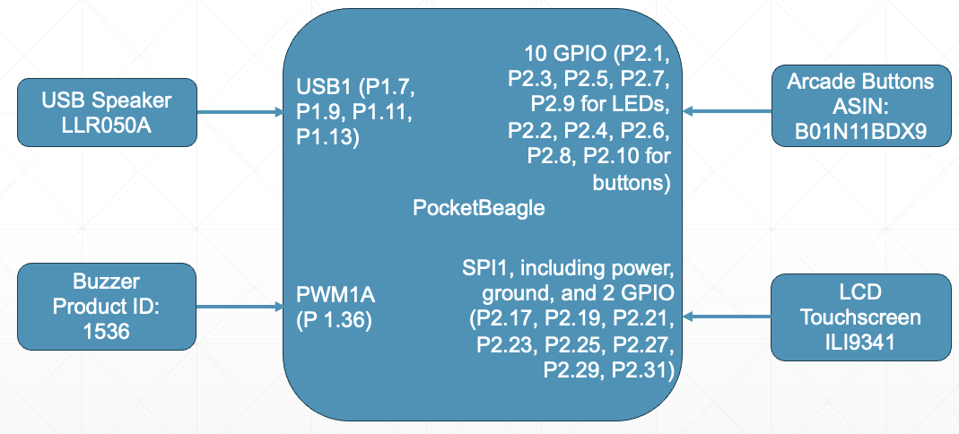
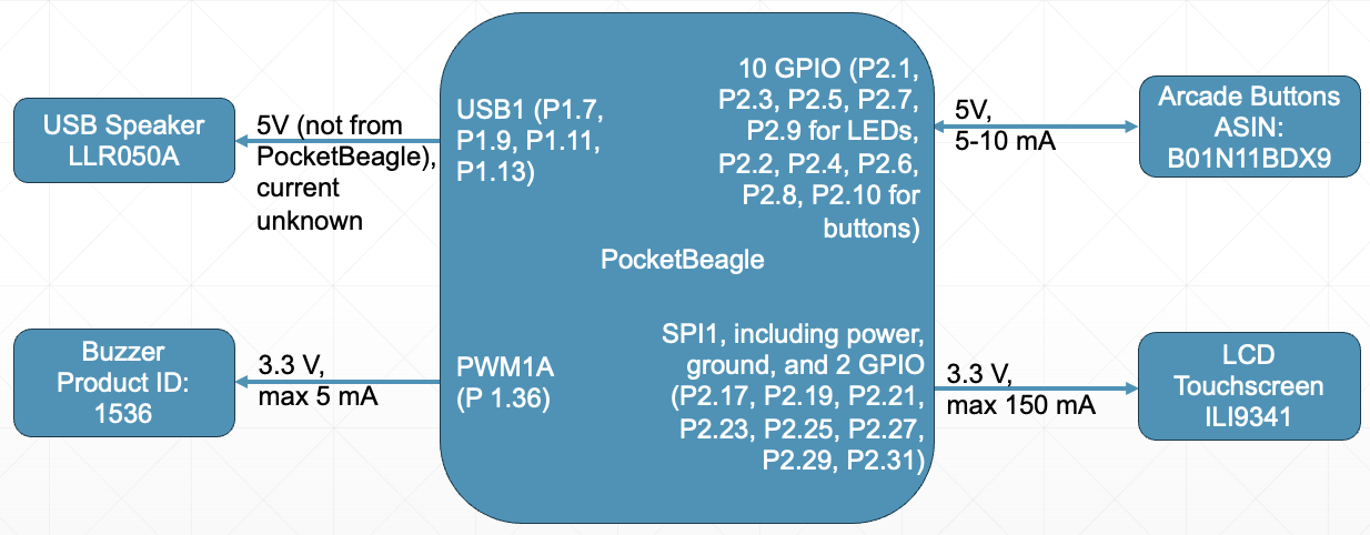
Building the One-Handed PianoBefore physically building the project, I created a system and power block diagram to plan how my components will be wired. The PocketBeagle pinout diagram was helpful throughout this process of deciding which pins I would use for my project.
Once I completed these planning stages and received all my hardware components, I began the wiring for my project. Here is an outline of the steps I followed to build my project's hardware.
First, I placed my PocketBeagle on a breadboard with P1.1 in column A, row 1 on the board.
Next, I wired up my USB adapter to attach my speaker to the PocketBeagle. To do this, I ran wires under the breadboard, connecting P1.7 to VIN (or VBUS depending on adapter labeling), P 1.9 to D-, P 1.11 to D+, and P 1.13 to ID (or GND depending on adapter labeling). Five pin adapters need an additional wire connecting ID to GND. Note that the PocketBeagle must have VIN soldered to VBUS and ID soldered to GND for these connections to work.
Next, I wired my SPI screen that displays game interface screens into SPI1 on the PocketBeagle. To do this, I used a black wire to connect P2.21 to GND. A white wire connected P2.23 to VIN. A yellow wire connected P2.29 to CLK. A green wire connected P2.27 to MISO. A blue wire connected P2.25 to MOSI. A orange wire connected P2.31 to CS. A red wire connected P2.19 to D/C. A brown wire connected P2.17 to RST.
Next, I added the buzzer that will buzz if the user plays the wrong note or waits too long to play a note. My buzzer was wired from PWM0A (P1.36) into the positive side of the buzzer. The other side of the buzzer was grounded. To ground the buzzer, I ran P1.16 to the negative rail of my breadboard.
Then it was time to build my LED arcade buttons that serve to display the light sequence and allow users to play the song. I wired the buttons on a second smaller breadboard. These buttons require 5V of power, so I ran P2.13 to the positive rail of this breadboard and P2.15 to the negative rail of the breadboard to provide power and ground to the buttons.
First, I had to solder four wires onto each button. The two pins that protrude from inside the button are for the LEDs. The anode and cathode are marked with a positive and negative sign, respectively. I wired the anode with a red or burgundy wire, and the cathode with a black or brown wire. The other two pins that protrude from the gray plastic piece are for the button. These are not directional. As such, I used two wires that were the color of the button for these pins.
Next, I wired the arcade buttons to interface with the PocketBeagle. For the LEDs I used a transistor-controlled LED configuration, allowing my buttons to easily run off of 5 V. To do this, I wired the anode of the LED to a 5 V power supply. The cathode of the LED was wired to enter the collector of an NPN transistor. The base of the transistor was in series with a 1 kOhm resistor and the GPIO pin for the LED (P2.1, P2.3, P2.5, P2.7, P2.9 for white, red, yellow, green, blue respectively). The emitter of the transistor was in series with a 1 kOhm resistor that was grounded.
The buttons were wired in the active high configuration. As such, a 1 kOhm resistor was wired to the 5V power supply. This resistor was in series with one pin from the button and the GPIO pin for the button (P2.2, P2.4, P2.6, P2.8, P2.10 for white, red, yellow, green, blue respectively). The other side of the button was grounded.
Now that all the wiring of my project was complete, I worked on the software for the one-handed piano. At a high level, I first tested all my hardware using the previously created drivers buzzer.py, screen.py, threaded_button.py, and led.py. Then, I created my project file one_handed_piano.py. This file takes in all of these drivers and two additional libraries I created for my project, songs.py (which is based off of buzzer_music.py) and color_button.py. My project also contains a configure_pins.sh file and a run script. Using cron, the code is set to run automatically on boot.
To develop my code, I created a user flow chart pictured below to conceptualize how users would interact with my device. My code allows the user to select from two modes: learn mode or practice mode. In learn mode, lights are lit up in a certain sequence, and the user must push the buttons in the correct order to play the song correctly. Each round adds on more notes, making the memorization harder. Additionally, the buzzer will buzz if the user makes a mistake or takes over five seconds to respond. The users can then decide to start over, enter practice mode, or power down the device. In practice mode, users are free to play notes as they please by pressing the desired button.
For more information and access to my code, visit the project_01 folder in my ENGI301 GitHub Repository.
Once I finalized the hardware and software for my project, I created a wooden box to house the components. To do this, I utilized a template from MakerCase and added appropriate holes on the top for the screen and buttons, as well as a hole on the right side for the cords from the speaker and PocketBeagle. The Adobe Illustrator file containing this box is attached.
To operate the device, follow these steps.
1) Plug the a microUSB cable into the side of the PocketBeagle. Plug the USB speaker into the USB adapter.
2) Plug the PocketBeagle cord into your laptop. This may require a USB-A to USB-C adapter.
3) After waiting a few seconds for the PocketBeagle to power up, ping the PocketBeagle via your device's terminal to ensure it is connected.
4) Navigate to Cloud9 by typing 192.168.6.2:3000 into your browser.
5) Follow the software operation instructions in the README.md file on my GitHub repository. Clone the repository, change to the correct directory, and type sudo./run to run the code. Note that you may have to change the run file to be executable using chmod.
6) Follow the prompts on the SPI screen to play the one-handed piano!
Here is a video demonstration of my one-handed piano project. First, I learn a few rounds of the song via learn mode. Then, I make a mistake intentionally to show what the project does when a user messes up. I enter practice mode to press a few buttons. I press and hold the red button to leave practice mode, and then I press the red button again to quit the program.
Future WorkThere are a couple areas I see for improvement in the future. First, there is a slight delay between when the user presses a button and when the speaker plays the note. In the future, I would like to make this connection more instantaneous. This may involve purchasing a higher-quality speaker, or making code modifications.
Currently, my project only allows users to play one note at a time. In the future, I would like to modify the code such that users can press down multiple buttons to play multiple notes and make chords on the one-handed piano. I would also like to add more songs in the future so that users can select which song they would like to learn.
Right now, my code only checks to see that the user presses the buttons in the correct order of the song. To make the game more complicated, I would like to implement a time dependence such that the user must be within a certain tolerance from the specified note length in order for that note to be counted as correct.
Lastly, I was originally planning to use a touchscreen for this project in order to move between learn and practice mode. However, classmates using the touchscreen aspect of the SPI screen noted that it was not very precise, which would be difficult given how I designed my screens with the options all in the bottom half. In the future, I could experiment with a larger or more precise touchscreen to add in this functionality.
AcknowledgementsI would like to give a huge thank you to Professor Erik Welsh for all his help throughout the process of this project. I would also like to thank Darrell Good for his help in laser cutting the box for my project. Lastly, I would like to cite the use of ChatGPT during the coding process for general coding ideas and troubleshooting tips.


Comments
Please log in or sign up to comment.