

The Arduino and Basic Stamp are 5 V devices, but many modern devices — sensors, displays, flash cards and the like — are 3.3 V only and require level conversion to protect them from higher voltage signals.
Level shifting for the I2C communication protocol uses a FET design following the NXP application note. This board should work with high voltages up to 10 V and low voltages down to 1.8 V.
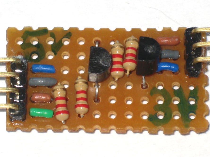
For ease of prototyping I used 2N7000 N-channel MOSFETs on strip board, and tried 2.2 K pull up resistors in the hope that they would allow slightly transfer rates than 10 K resistors used in the equivalent Adafruit PCB.
The design fits on 6 strips x 8 holes. I used a slightly wider board to make room for colour coded loops of wire next to the right angle pin headers. The SDA and SCL lines are marked brown and grey. The low voltage can be supplied on either side of the board (blue line).
The grounds on the two devices also need to be joined. This can be accomplished on the board with a simple change to the design.
Schematic and layout- Stripboard I2C Logic level converter by Dangerous Prototypes on 2013-09-02
Comments
Please log in or sign up to comment.