A heart rate monitor is a device used to monitor the rate of heartbeats in human beings. The heart rate is expressed in units of number of beats per minute (BPM). The heart rate of a human body varies depending on daily physical activities, sleep, and general health. Keeping track of heart rate during physical exercises enables people to ensure the safety of their fitness program. The normal heart rate for a person during rest is 60-100 BPM. However, the rate increases when the person does physical activity.
Reference: http://embedded-lab.com/blog/heart-rate-measurement-from-fingertip/
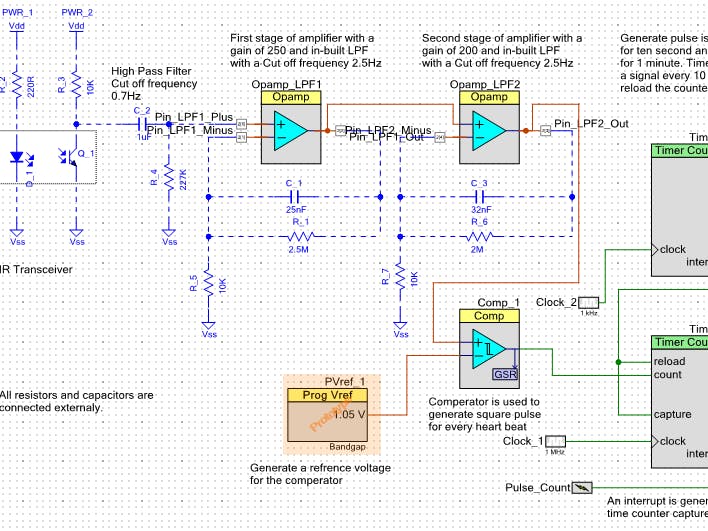
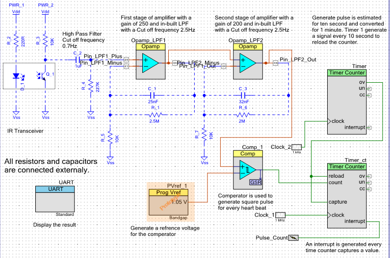
Design ProcedureThis project demonstrates a technique to measure the heart rate by sensing the variation of the blood volume inside a finger artery, which is caused by the pumping action of the heart. It consists of an infrared LED that transmits an IR signal through the fingertip of the subject. A portion of this infrared light is reflected by the blood cells. The reflected signal is detected by a photo diode sensor. The changing blood volume with heartbeat results in a train of pulses at the output of the photo diode, the magnitude of which is too small (50-70uV) to be detected directly by a microcontroller. Therefore, a two-stage, high gain, amplifier is required. Obtaining a gain of 50,000 typically requires cascading two amplifiers (e.g., of gains 250 and 200). Thus two op-amps can be used to design a amplifier with an overall gain of 50,000.
There are many possible noise sources to be considered when designing such equipment, a few of which are: measurement (or body contact) noise, electromyogram (EMG) noise (muscle contraction), and movement artefacts (common while doing physical activities). These noises from high frequency sources have to be eliminated using a 1st or 2nd-order low-pass filter.
Finally, to generate a square wave train so as to count the number of pulses, we need to feed the output of the two stage amplifier to a comparator with a suitable threshold. Note that the threshold depends on the IR transmitter and receiver used.
Now, the comparator generates a series of pulses of the same period as our heart beat. We need to feed this output to a digital block or an MCU (microcontroller unit) to count the number of pulses per minute and thus display the resultant output on an LCD.
From the above description, we see that we need:
1. Heart rate sensor (IR diode and IR receiver pair)
2. Three external op-amps: two in the filtering and amplifying stage, and one as a comparator
3. One MCU to count the heartbeat rate and control the display unit. If the MCU cannot directly drive the LCD, an external chip will be required
4. One LCD to display the heart rate.
To reduce component count, a single low-cost programmable system on chip such as the PSoC Analog Coprocessor Pioneer Kit from Cypress can replace the op-amps needed in this application as well as the MCU and LCD interface. Featuring the low-power ARM Cortex-M0 core, combined with programmable mixed-signal hardware, this chip provides a flexible and scalable low-power mixed-signal architecture capable of meeting the analogue I/O, signal processing, and real-time computational requirements of this type of application.
The complete schematic is attached in the schematic section. Opamp 1 & 2 are using here as low pass filter with gain.
Filter capacitors and resistors are connected externally.
The output of the amplifier stage has to be fed to a comparator to generate a train of square wave signals whose frequency is proportional to the heartbeat rate. Dedicated comparator blocks perform this operation.
A highly accurate 1.05V reference is used for the Analogue to Digital Converter (ADC). This same voltage source can be fed to the negative terminal of the comparator block.
The pulses coming out of the comparator block can be fed into a counter block (dedicated TCPWM block in PSoC 4) to count the number of pulses occurring per minute.
I soldered all the external filter capacitors, resistors and sensor into a perfboard. I attached pin header to with it to connected the circuit with PSoC board.
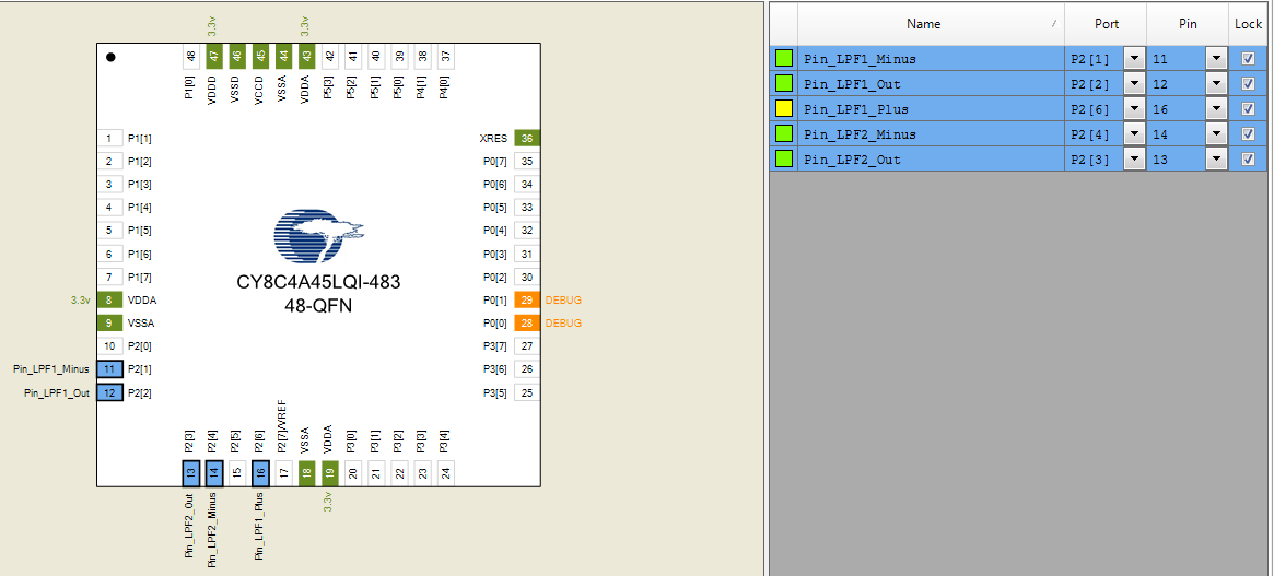
Then I connected the sensor and filter circuit to the PSoC board with jumper wires.


Comments
Please log in or sign up to comment.