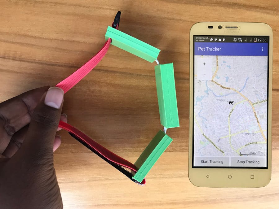
According to the American Humane Association over 10 million dogs and cats are lost and stolen in the U.S. every year. Equipping pets with ID tags or microchips is one way to ensure your pets’ safe return in case they get lost while on vacation or stray away from home, but you can take your dog’s safety to another level — with wearable tech for pets. Pet wearables, such as GPS collars, are making it possible for pet parents to track their doggo’s location (and even monitor their activity) wherever they are.
The working principle of pet tracker is very simple. A GPS chip in the tracker acquires your pet’s position and sends the info to the internet and your smartphone primarily via cell coverage. Usually, an app is used to display your pet’s location on a map.
Though different types of pet trackers are available in the market most of them are expensive. Besides, it is always a pleasure for a maker and hobbyist to make something by themselves. By following this tutorial you will be able to make a pet tracker by yourself.
How to Make OneSeveral tasks are involved in making a pet tracker which includes:
a. Selecting appropriate hardware
b. Connecting hardware
c. Developing Program
d. Developing smartphone application
e. Designing case
Selecting Appropriate HardwareChoosing appropriate hardware is very important task for any project. For designing a wearable product form factor, weight and power management are very important. For the pet tracker weight and size should be as less as possible. As it is a battery operated device, battery backup time should also be considered seriously. There is a trade-off between battery capacity and battery size. Keeping all the parameter in mind I selected the following hardware for the project.
For making a pet tracker you need a microcontroller, GPS and data communicating device. I selected Sony Spresense Board for my project and the reason for selecting this is very obvious. It has a built in GPS with the microcontroller, small form factor and is very power efficient. For data communication I have chosen SIM800 GPRS module. For powering the device I took a 300mAh li-ion battery. For Li-ion battery charging a Li-ion charger module is also required.
For making the devise usable I designed separate 3D printed box for Sony Spresense board, SIM800 module and battery. Three units will be connected with flexible wires so that it can easily fit to the pet collar.
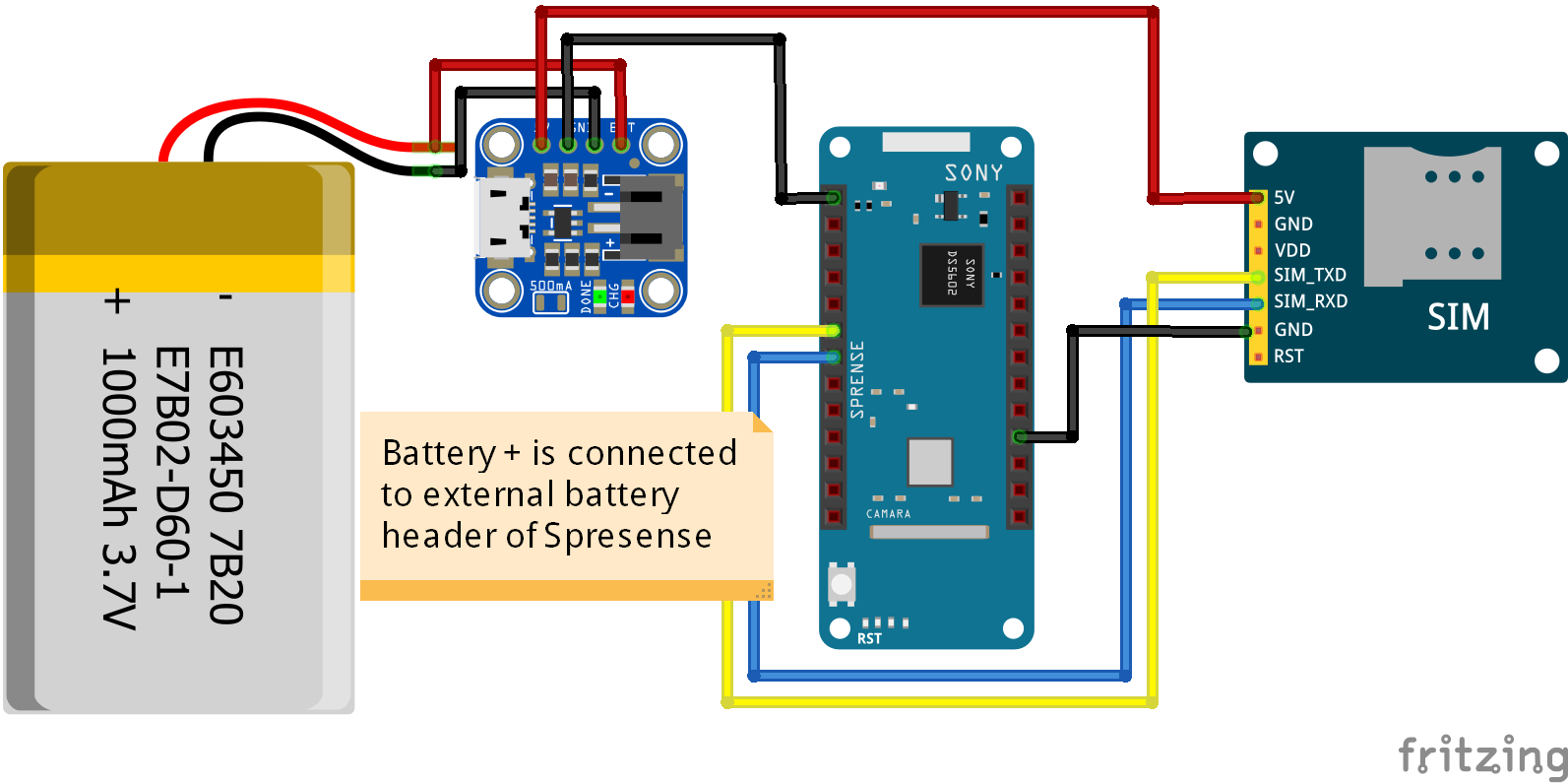
Connecting hardware correctly is also a very important job. If you make any mistake on connection you may burn your hardware especially if you make reverse connection between supply and ground. Figure shows the connection diagram of my project. You may change the connection between Spresense board and SIM800 module but you need to make some change on the code accordingly.
The spresense board is connected to the battery through the external battery connector. The battery and charger circuit was placed inside the 3D printed battery box. Two wires are bring out to connect with spresense board.
For uploading data to cloud server I used GPRS data communication technology and a low cost small size SIM800 module was used for this purpose. TX and RX pin is connected to two GPIO of spresense pin, 5V pin is connected to 5V pin of the charger circuit and GND pin is connected to a ground pin of the Spresense board.
Four wires are brought out from the case to connect spresense board. Connection among all three main components are given below. All are placed inside the individual box. After making the connection completed it is the time to write program for the spresense board.
For developing program using Arduino IDE I started with the gnss example code provided with the spresense core. I modify the code to read only longitude and latitude in every second if user enable the tracking option. Otherwise GPS module will be on sleep mode and it will increase backup time. SIM800 module communicate microcontroller using serial port and I used software serial library of Arduino to connect SIM module with spresense board. For storing the data Ubidots IoT cloude was selected. SIM800 module uploads the data to Ubidots using HTTP protocol and it is implemented in code using direct AT command without using any library to make it compatible with spresense board.
For remote tracking a cloud service is required and Ubidots cloud was chosen for this purpose. I created a device and three variables under the device for collecting and storing data from pet tracker. Two variables are for longitude and latitude. Rest one is for enabling the tracking functionality from from the tracker. This variable collects data from user through mobile app. When user press Start Tracking button it sends a flag value 1 to the cloud. Spresense board receive the value and start reading and uploading the GPS coordinates. If user press Stop Tracking button 0 is sent to the cloud as well as spresense board and presense board stop reading and uploading the GPS coordinates.
For tracking the pet a visual interface like smartphone application is required. I developed an android application using MIT App Inventor. It is an easy and free web platform for designing android application without knowing any programming. I added one map view and two button in the UI interface of the program. Map shows the position of the pet according to the received coordinates from the Ubidots cloud. User can start and stop the tracking from the two buttons. The complete source code (.aia) file is attached on the code section so that you can download any modify the application according to your choice and requirement.
After finishing all the previous steps I added a velcro band with the device so that I can attach the tracker easily with the pet’s collar. This tracker can also be used to help you find your car or other items – anything you want to track, simply attach it and use the app to help you find it.


_3u05Tpwasz.png?auto=compress%2Cformat&w=40&h=40&fit=fillmax&bg=fff&dpr=2)
Comments