


Hardware components | ||||||
 |
| × | 1 | |||
 |
| × | 1 | |||
 |
| × | 1 | |||
 |
| × | 1 | |||
 |
| × | 1 | |||
 |
| × | 1 | |||
 |
| × | 1 | |||
 |
| × | 1 | |||
 |
| × | 1 | |||
 |
| × | 1 | |||
 |
| × | 1 | |||
| × | 1 | ||||
| × | 1 | ||||
| × | 1 | ||||
| × | 1 | ||||
 |
| × | 1 | |||
Hand tools and fabrication machines | ||||||
| ||||||
 |
| |||||
 |
| |||||
 |
| |||||
 |
| |||||
 |
| |||||
| ||||||
I love upcycling old equipment and modifying it to give it a new lease of life.
This project is part of a series on modifying Vivitar 283 speedlights for off-camera use as studio strobes.
The Vivitar 283 is the most popular electronic flash unit in the history of 35mm photography. It was in production for 30+ years from the 1970s onwards at a time before TTL (Through The Lens) flash metering was affordable.
It’s durable, powerful, simple to use with four auto f-stop settings for controlling depth-of-field, a bounce head and a flash range of less than 1m to over 13m (guide number 120 at ISO 100). Vivitar also manufactured a large range of accessories including lens kits, filter kits, off camera sensor cables and external power cords.
Crucially, it was relatively inexpensive when new and this plus the long product production life means that they remain cheap and readily available on eBay despite still being in demand. They are highly prized because of they can sync at high speeds (less than 1/8000 second) and the plug-in design of the sensor means that they can be modified in a non-destructive way.
On challenge is that "out of the box" there is no way to manually control the power of the flash. Vivitar did produce a plug-in variable power controller but it was hard to get reproducible results. As a consequence it didn't sell very well which makes them quite rare.
Making Your Own Manual Power ControllerLet me start by saying that I am by no means the first person to make a manual power controller for the 283. There were folks sharing designs in the electronics magazines in the 1980s.
The most useful resources I’ve found are by Charles Krebs and by John Robinson and I have borrowed heavily from both.
Replacing the “Auto Thyristor” Sensor
The 283 has a plug-in light sensor on the front. The resistance of this sensor changes depending on the amount of light. When the 283 is mounted on the camera, the sensor measures the reflected light and turns off the flash when sufficient light has reached the camera.
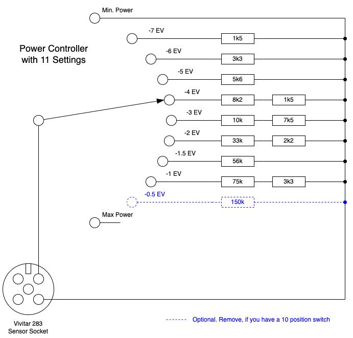
The original Vivitar variable power accessory replaces the sensor with logarithmic potentiometer. In this project, I'm setting the resistance using a rotary switch and a set of resistors. This allows you to dial-in the power you want in a straightforward and repeatable way which is essential when trying to balance multiple strobes during a photo shoot.
The Resistors Values
The resistor values have been chosen to allow the the "power" of the flash to be manually controlled in 11 steps from full power and minimum power.
Changing the resistance doesn't affect the peak light intensity of the flash, that remains constant. Instead changing the resistance changes the duration of the burst and therefore the amount of light it contributes to the overall exposure.
At high resistance (250K ohm or greater) the flash is a "full power" and has a duration of 1/2, 000 second (0.5 ms). At very low resistance (less than 100 ohms) he flash is a "minimum power" and has a duration of around 1/30, 000 second (0.03 ms).
In photography, exposure value (EV) is a number that represents a combination of a camera's shutter speed and aperture (f-number), such that for a scene with a fixed luminance, all combinations that yield the same exposure have the same EV. For example, if a combination of shutter speed and aperture have an EV of 11, then increasing the shutter speed by one stop and opening the aperture by one stop (smaller f-number) will also provide a combination that has an EV of 11.
Exposure values were more widely used in the past and aren't so important in the world of digital photography where you can immediately see the results and adjust your settings accordingly.
My hobby is black and white film photography and being able to make adjustments based on adding and subtracting EVs is really helpful and prevents a lot of wasted time and wasted film.
The resistor values were chosen to provide a systematic reduction in power in 0.5 EV and 1 EV steps:
- Full power
- 3/4 power (approx. -0.5 EV)
- 1/2 power (approx. -1 EV)
- 3/8 power (approx. -1.5 EV)
- 1/4 power (approx. -2 EV)
- 1/8 power (approx. -3 EV)
- 1/16 power (approx. -4 EV)
- 1/32 power (approx. -5 EV)
- 1/64 power (approx. -6 EV)
- 1/128 power (approx. -7 EV)
- Minimum power (approx. -8 EV)
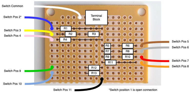
The build is straightforward provided you use a different coloured wire for each switch position. If you don't, then you can easily end up connecting the resistors to the switch in the wrong sequence.
I find that cutting the wires to 7-8cm lengths before stripping the ends is a good balance. Cutting them shorter makes soldering the connections to the PCB challenging. Cutting them longer makes it difficult to fit all the wires in the plastic enclosure.
Using an experiment PCB with lanes and islands simplifies the need to solder some resistors in series; and needing to connect one end of each resistor or group of resistors to the same pin on the terminal block.
Before soldering each resistor group, I double check the values with a multimeter. It's quicker than having to de-solder them, if I make a mistake.
Steps
1. Cut 11 lengths of wire about 8cm long
2. Strip around 1cm at each end of each wire
3. Wrap the stripped of one wire around the first pin on the switch and solder it in place.
4. Repeat step 3, until you have soldered a different coloured wire to each of 11 pins on the switch. Position 1 (full power) does not have a wire soldered to it. As a guide you can use the colours shown in the PCB layout
5. Careful saw the experiment PCB in half, parallel to the short side of the board
6. Lay the resistors on the board. Resistors R5, R7 and R9 need to be mounted vertically. The remaining resistors should be laid flat against the PCB
7. Using the multimeter, check each resistor against the circuit diagram and the PCB layout, to ensure they are all in the correct location
8. Solder each resistor in place and then cut off any excess wire
9. Fit the terminal block on to the PCB with the screw holes facing out. One pin from the terminal block should be in the same PCB lane as the resistors
10. Solder the terminal block to the PCB
11. Using the multimeter, place one probe on the terminal block whose pin is soldered to the lane connected to the resistors. With the other probe, check the resistance at each location on the PCB that will have a wire soldered to it.
You can use the values listed in step 15
12. Solder the common wire (white in the PCB layout diagram) to the PCB
13. Turn the switch to minimum power (position 11) and solder the wire for that pin to the PCB (black in the PCB layout diagram)
14. Using the multimeter, check the resistance between the two screws on the terminal block. (For minimum power the resistance should be zero.)
15. Repeat steps 13 and 14 working from position 10 to position 2
Use these values as a guide (the resistor values can be out be +/- 1%):
- Position 11: 0 ohms (black)
- Position 10: 1.5 Kohms (blue-green)
- Position 9: 3.3 Kohms (green)
- Position 8: 5.6 Kohms (orange)
- Position 7: 9.7 Kohms (red)
- Position 6: 17.5 Kohms (grey)
- Position 5: 35.2 Kohms (brown)
- Position 4: 56 Kohms (pink)
- Position 3: 78.3 Kohms (yellow)
- Position 2: 150 Kohms (blue)
16. Drill holes in the lid of the case to allow the switch to be fitted
17. Drill a 4mm hole in one end of the case to allow the sensor cable to enter
18. Cut, strip and attach the sensor cable to the terminal blocks (see the nest section)
19. Carefully, fit the switch to the lid of the case
20. Carefully, fit the PCB into the bottom of the case. If you are using a similar case to mine then you can use a single screw, otherwise use a sticky pad or a hot glue gun
21. Carefully fit the lid to the case making sure not to trap any of the wires
22. Optionally, paint dots on the lid of the case to show the switch positions using an acrylic paint pen. I use a red dot for full power, yellow dots for the 0.5 EV steps and white dots for the full 1 EV steps
Now, take a moment to admire your works and clean up your work bench before plugging it into your Vivitar 283 and testing it.
Connecting the Power Controller to Your Vivitar 283The controller can be connected using two male-male DuPont jumper wires. One end of each needs to be screwed into the terminal block and the other end pushed into the sockets on the right hand side of the sensor socket.
A more durable and aesthetically pleasing solution is to cut down a Vivitar SC-1 remote sensor cord. The 1.2m cord has a socket for the sensor at one end and a plug that fits into the sensor socket, at the other end.
In Europe a remote sensor cable currently goes for less than €15 on eBay including delivery. I cut a 25-30cm length of cable including the plug. I feel a bit bad about cutting them but it's in a good cause.
The cord has three coloured wires (blue, red and yellow) and a spiral shield. The power controller needs to be connected to the blue wire and the spiral shield. It doesn't matter which one you connect to which terminal block but I generally connect the blue wire to the common pin on the switch. The red and yellow wires are unused and can be cut short.
Before you connect the wires to the terminal block, tie a knot in the sensor cable inside the case to act as a strain relief.
TestingSince the Vivitar 283 will happily cope with both an open connection between the sensor pins as well as the sensor pins connected to each other a jumper cable then it's hard to accidentally damage it.
Testing is focused on ensuring that the resistors are connected to the switch in the correct sequence.
I start with minimum power and take a series of images in manual mode, checking that the latest image looks slightly brighter than the previous image.
ResultsA series of photos showing the different power levels.
The photos were taken with the Vivitar 283 mounted in a 60cm x 60cm softbox.
The photos were taken using a Nikon F80D with a 50mm lens and Fomapan 100 film (ISO 100) with an aperture of f4 and a shutter speed of 1/60 second.


Comments
Please log in or sign up to comment.