Introduction
The challenge that a lot of Formula SAE teams encounter when designing their intakes is how long they should make their runner. A runner is the actual tube that connects the intake (plenum) and the intake ports. Theoretically the longer the runner is the more power the engine will make at lower rpms. Whereas, the shorter length runner will make more power at a higher rpm. However, we would like to find a middle ground between these to get the best power we can at high and low rpms. In order to test this we have decided to make a Variable Runner Length Data Acquisition Unit That will be used in conjecture with our Eddy Current Dynamometer and KTM 450cc engine.
We split the project into two main circuits. The first circuit was a Wireless meant to allow whoever is controlling the dyno to adjust the runner length without going into the same room as the engine while its running. The circuit will then be connected to a second circuit known as the Data Acquisition Unit. The Data Acquisition Unit's main purpose is to control the actuator and collect data.
The circuits used in the Wireless Controller, and the Data Acquisition Unit are shown in the Schematics section of the project.
Wireless Controller
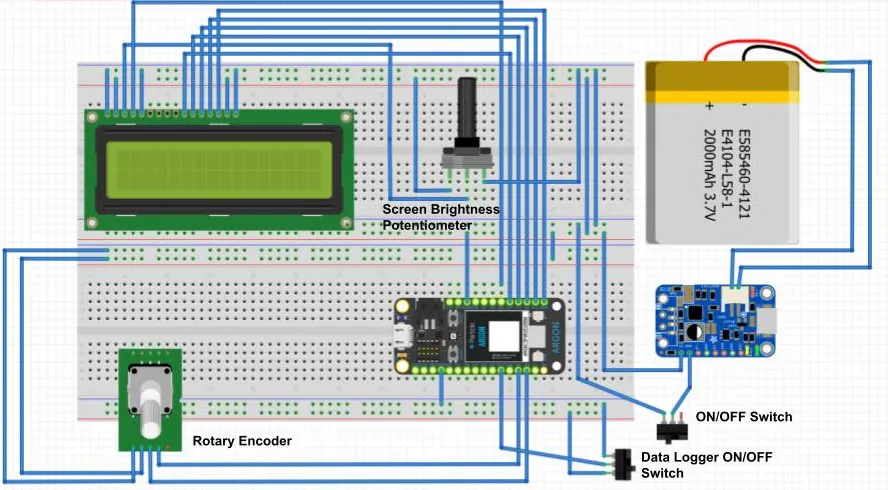
Figure 1: Completed Wireless Controller
The components used in the Wireless Controller's circuit includes:
- potentiometer
- Rotary encoder
- LCD display
- battery for remote power
- Adafruit USB Li-Ion Battery Charger
- 2 on/off switches
- Particle argon.
The Circuit for the Wireless Controller was built on a custom protoboard and was sized to fit our custom 3D printed enclosure (Figure 1). The first on/off switch turns on the power from the battery and runs to the argon and LCD display. Once turned on the LCD display will display what length the runner is actually set at. The value can be adjusted through the rotary encoder that will send a signal through the particle argon and into the cloud to the Data Acquisition Unit to tell it to adjust the length and when it sends a signal back it will then change the LCD's value. There is also a switch to allow us to turn on/off the data logging program, as well as a custom Li-Po circuit that allows us to charge the battery while everything is plugged in.
Data Acquisition Unit
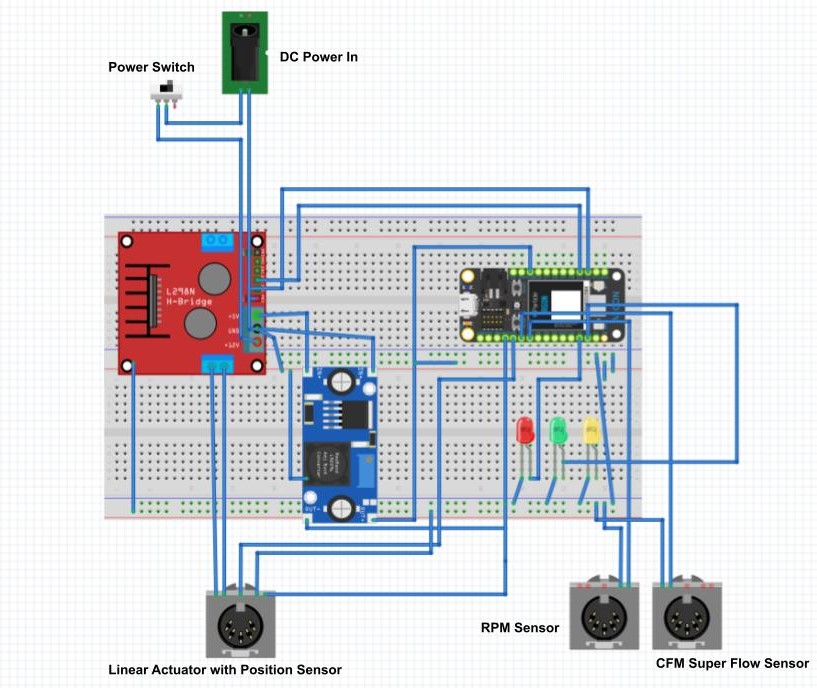
Figure 2: Data Acquisition Unit
The components used in the Data Acquisition Unit includes:
- RPM Sensor
- Superflow Volumetric Flow Sensor (CFM)
- 150mm Linear Actuator with Position Sensor
- H-bridge Motor Controller
- DC Buck Converter
- DC Power Switch
- DC Barrel Connector
- 3x LED lights
- Particle Argon
Just like in our wireless controller the Data Acquisition Units circuit was created on its own custom protoboard and enclosed in a custom 3D printed enclosure. The Data Acquisition Unit houses most of the sensors for the project. The three main sensors that we used for the project are a RPM Sensor, Linear Actuator with Position Sensor, and a Volumetric Flow Sensor. The RPM Sensor (Figure 3) gets its signal from the KTM 450's crank position sensor. The signal is then sent to our custom MATLAB script where it is analyzed to allow us to calculate the theoretical Mass Air Flow of the project.
The second sensor that we used in our project was the Volumetric Flow Sensor made by Superflow (Figure 4). This sensor is used to record CFM data that will be used to calculate our actual Mass Air Flow. Using the MATLAB script we can then use the actual and theoretical Mass Air Flow to get our volumetric efficiency throughout the RPM range.
Figure 4: Superflow Volumetric Flow Sensor
The final and most important sensor that we used in our project was a 150mm Linear actuator with a position sensor (Figure 5). The actuator works in conjunction with the Wireless Controller to adjust the Variable Runner Length. The runner receives a signal from the the Rotary Encoder that is apart of the Wireless Controller and adjusts its length based off of that signal. It then sends another signal back to the Wireless Controller to update the LCD display with the new dimension.
Figure 5: 150mm Linear Actuator with Position Sensor
Custom Variable Intake
Figure 6: Custom Variable Runner intake for Dyno Testing
Figure 3 shows a CAD render of what the custom 3D printed variable runner intake that was designed to work with the linear actuator to allow us to fully demonstrate and test for the optimal runner length for a 450cc engine.
Communication
Figure 7: Particle Argon communication Flow Chart
Data Logging
In order to to calculate the most optimized runner length. We take the CFM data from the Volumetric Flow sensor, the RPM data from the RPM Sensor, and the Actuator's current length data (Figure 8). This data was recorded in the Data Acquisition Unit after which it can be opened in MATLAB where our code will Calculate Theoretical Air Mass Flow from the RPM data, and Actual Air Mass Flow from the CFM data. It is then put together to calculate the overall Volumetric Efficiency at each runner length and RPM. It is then plotted on the graph shown in Figure 9.
Figure 8: starting Runner Length, CFM Data, and RPM being calculated
Figure 9: Volumetric Efficiency at each length and RPM.
Video Submission
Conclusion
Our overall goal of creating a Variable Runner Length Dyno Data Acquisition Unit that will allow us to find the most optimized runner length to achieve the largest Volumetric Efficiency value for 49ers Racing's FSAE car was accomplished through this project. In our video submission above we demonstrate how the dyno user can remotely adjust the intakes runner length from the control room without having to go into the dyno room, and what it looks like when data is being collected from the RPM sensor, Linear actuator, and Volumetric flow sensor live from the engine and how it is converted to Volumetric efficiency in MATLAB, and finally plotted into a graph.


_zhWsCcSEcl.jpg?auto=compress%2Cformat&w=48&h=48&fit=fill&bg=ffffff)


_3u05Tpwasz.png?auto=compress%2Cformat&w=40&h=40&fit=fillmax&bg=fff&dpr=2)
Comments
Please log in or sign up to comment.