The University of North Carolina at Charlotte offers a course, MEGR 3092: Special Topics in Engineering. In the Spring of 2023, the special topic was Control of Electric Drivetrains. This class taught students concepts for power and control systems that the automotive industry implements in electric vehicles. The students then implemented these concepts themselves on a smaller scale, introducing microcontrollers, power monitoring, variable throttles, and traction control into low voltage, ride on toys such as Power Wheels.
We are team 5, and we modified a used Barbie edition Cadillac made by Fisher Price. The project began with upgrading from the stock 12 volt lead-acid battery to a 24 volt, 2 amp-hour lithium ion drill battery, and implementing voltage and current monitoring to the system. Next, variable speed was added with a Hall effect pedal and PWM speed controllers. Finally, basic traction control was implemented via controlling the slew rate of the motors.
BatteryUpgrade
The battery change began with disassembling the Kobalt power adapter and drilling holes in the plastic case for wires to be attached to the battery leads on the interior PCB. 12 gauge wires were soldered to the PCB battery leads, fed through the holes in the plastic case, and the whole thing was reassembled, now with extra battery leads. The 12 gauge wires were trimmed at offset lengths and two male quick-disconnect terminals were crimped onto the wire ends to try to avoid the battery being shorted. The two wire battery connector on the car was cut off at a complimentary offset, and two female quick-disconnect terminals were crimped onto the wires in the car. The quick-disconnect terminals were connected and loosely taped over to further block accidental shorts, and the Kobalt drill battery can be quickly slid into and out of the adapter with ease.
The Kobalt power adapter was chosen for the easy connection to the drill battery, and for the 5 volt USB outputs. The hope was to use a USB output to power the Argon, but an accidental short while testing the battery/adapter setup broke the USB output function before this idea could be tested. We then alternated between using a power bank and using the laptop that the code was written on to power the Argon. Using the laptop allowed for tuning the code on the fly for throttle sensitivity and slew rates.
PowerMonitoring
Monitoring the current and voltage outputs of the battery involved splicing the ACS758LCB current sensor into the positive wire coming off the battery and constructing a simple voltage divider circuit in parallel with the rest of the power circuit using two high-impedance resistors.
To monitor the current, the positive wire from the car (downstream of the quick-connect terminals) was cut and ring terminals were crimped onto both cut ends, which were then screwed onto the IP+ and IP- terminals of the current sensor. The Argon was inserted into the included breadboard, and small wires were inserted leading the Argon 3.3 Vcc and ground pins to the positive and ground channels on the side of the breadboard. Jumper wires from the current sensor 5 Vcc, ground, and analog Vout pins were lead into the positive channel, ground channel, and Argon A2 pin, respectively. (Note that our current sensor, and the motor drivers later on, work at 3.3 Vcc, even though they say 5 Vcc. The 5 Vcc pin marking is a maximum, so you don't fry the module trying to power it with a 24 volt drill battery for example, but will usually work at either microcontroller-level power output.)
The voltage divider circuit was made in the breadboard by connecting the positive channel to one end of the 100 kiloohm resistor, the other end of the 100 kiloohm resistor to both the 10 kiloohm resistor and the Argon A1 pin, and the other end of the 10 kiloohm resistor to the ground channel. This voltage divider cuts the 24 volts of the battery to a maximum of about 2.2 volts, safely within the Argon's 3.3 volt limit, and only uses about 0.2 milliamps of current, so the error from the current sensor is negligible.
The Argon analog pins map voltage from a 0-3.3 V scale to a 0-4096 bit scale, and the current and voltage sensors have their own associated scaling values. The voltage circuit had a scale value of 11 built in, and using a magnetic ammeter the scale value of the current sensor was determined to be about 8.5. These scales were accounted for within the Particle code.
VariableThrottle
A variable throttle was implemented using a hall effect pedal, the original pedal switch from the car, and 2 PWM DC motor controllers. A hole was cut into the floor of the car on the right side and the hall effect pedal was bolted in. Appropriate lengths of 16 gauge wire were cut, spade terminals crimped onto one end of each wire, male jumper wires spliced onto the other ends, and the pedal connected. One prong each of the spade terminals were bent and the other prong inserted into the pedal connector. The pedal 5 Vcc, ground, and Vout wires were connected to the positive channel, ground channel, and Argon A3 pins respectively. The high and low outputs were taken using a short Argon publish code. The output was dropped in the code by a little over the minimum value to allow for determining when the pedal was pressed, and then scaled from the input range of 0-2800 to the PWM range of 0-255 when it is pressed.
The original switch pedal from the car had male quick-disconnect ends, so two wires of a good length were cut and female quick-disconnects crimped to one end each and male jumpers spliced to the other ends. The wires were connected to two of the switch terminals (there are 3 terminals on the switch, but the two that make the larger gap are the live ones), one wire was connected to the positive channel, and the other wire was connected to the Argon A4 pin. When the A4 pin receives 3.3 volts, it knows the switch is activated and the car should reverse.
The motor controllers were inserted by cutting out the original speed switch, splitting the battery positive and ground wires into two, feeding those into the battery positive and ground on the speed controllers, and feeding the positive and ground of the left and right motors into the left and right speed controllers respectively. The BTS7960 motor drivers required 3.3 Vcc input into 3 of their pins: 5 Vcc, R_EN, and L_EN (powering the R_EN and L_EN enables forward and reverse polarity to the motors), which were all connected to the positive channel. The ground pin was connected to the ground channel, the RPWM and LPWM pins for the left controller were connected to the Argon's D2 and D3 pins, and the RPWM and LPWM pins were connected to the Argon's D5 and D4 pins. In the code, the scaled PWM signals from the pedal are sent to the RPWM pins for forward or LPWM pins for reverse.
TractionControl
Traction control was implemented in a basic way via slew rates. More involved traction control would involve wheel speed sensors, but this project just used an adjustment to the Particle code to limit the maximum throttle increase per program loop. The car was tested on a metal surface with no traction control implemented, and the rear tires slipped a lot before the car got moving. Implementing a slew rate of 5, meaning the PWM signals increased by a value of 5 every loop until the throttle input was reached, reduced the slippage but did not entirely remove it. Lowering the slew rate to 2 gave the best results, with almost no slipping of the rear tires. On concrete, even with no traction control the wheels did not slip any, but on a slicker surface such as the metal plate the car accelerated off the plate faster with the slew rate implemented, even though the wheels were limited in how fast they could spin up.
Results
Figure 1: Screenshot of Adafruit dashboard
Figure 1 shows our Adafruit dashboard, which the Particle sends power and throttle data to via webhooks. This dashboard can be seen here.
Video testing of the variable speed controls
Figure 2: Control system block diagram
In this control block diagram, the solid lines are the program progression and the dotted lines indicate data comparisons for decision making.
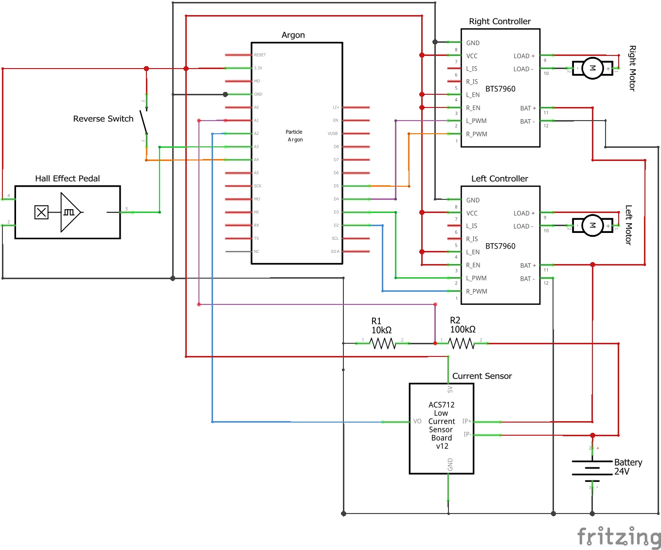
This is the wiring diagram for our car. The red lines indicate power, the black indicate ground, and the other colors indicate signal and control wires.
This is the initial Particle code for gathering, filtering, and uploading the voltage and current being output by the battery. The Argon connects to a pre-defined WiFi connection and uploads the data to the Particle cloud, which is then sent to an Adafruit dashboard through webhooks.
#define voltage A1 //define pins for current, voltage sensors and pedals#define current A2intvoltageValue;//declare variables for power readingsintcurrentValue;floatfilteringCurrent=0;//declare variables for low pass filteringfloatfilteringVoltage=0;floatfilteredVoltage=0;floatfilteredCurrent=0;floatvoltageCalibration=3.3/4096*11;//declare power calibration valuesfloatcurrentCalibration=3.3/4096*8.5;unsignedlongupload=10000;//declare reading and filtering intervalsunsignedlongmeasure=20;unsignedlonguploadTime=0;//declare reading and filtering timersunsignedlongmeasureTime=0;unsignedlongcurrentTime=millis();//declare time to compare to timersintfilterCoef=0.905;//declare 5Hz filter coefficientvoidsetup(){Serial.begin(9600);//start serial behavior and connect to wifiWiFi.on();WiFi.connect();}voidloop(){currentTime=millis();//get time to compare to timersif(currentTime-measureTime>=measure)//reads and filters current & voltage{voltageValue=analogRead(voltage);currentValue=analogRead(current)-480;measureTime=currentTime;filteringVoltage=filterCoef*filteredVoltage+voltageValue*voltageCalibration*(1-filterCoef);filteredVoltage=filteringVoltage;filteringCurrent=filterCoef*filteredCurrent+currentValue*currentCalibration*(1-filterCoef);filteredCurrent=filteringCurrent;}if(currentTime-uploadTime>=upload)//publishes current, voltage, and throttle values{Particle.publish("Voltage",String(filteredVoltage));Particle.publish("Current",String(filteredCurrent));uploadTime=currentTime;}}
Variable Throttle Code
C/C++
This is our updated code with variable throttle controlled via a simple switch for reverse and the Hall effect throttle pedal.
#define voltage A1 //define pins for current, voltage sensors and pedals#define current A2#define pedal A3#define reverse A4#define leftForward D2 //define pins for speed controllers#define leftReverse D3 //BTS7960 drivers have separate pins--#define rightForward D5 //--for forward and reverse#define rightReverse D4intvoltageValue;//declare variables for power readingsintcurrentValue;intpedalVolts;//declare variables for throttle controlintthrottle;booleanisReverse=false;//declare boolean for reverse switchfloatfilteringCurrent=0;//declare variables for low pass filteringfloatfilteringVoltage=0;floatfilteredVoltage=0;floatfilteredCurrent=0;floatvoltageCalibration=3.3/4096*11;//declare power calibration valuesfloatcurrentCalibration=3.3/4096*8.5;unsignedlongupload=10000;//declare reading and filtering intervalsunsignedlongmeasure=20;unsignedlonguploadTime=0;//declare reading and filtering timersunsignedlongmeasureTime=0;unsignedlongcurrentTime=millis();//declare time to compare to timersintfilterCoef=0.905;//declare 5Hz filter coefficientSYSTEM_THREAD(ENABLED);//enable threading so throttle works w/out wifivoidsetup(){Serial.begin(9600);//start serial behavior and connect to wifiWiFi.on();WiFi.connect();pinMode(leftForward,OUTPUT);//set pin modes for PWMpinMode(leftReverse,OUTPUT);pinMode(rightForward,OUTPUT);pinMode(rightReverse,OUTPUT);}voidloop(){currentTime=millis();//get time to compare to timerspedalVolts=analogRead(pedal)-1300;//read voltage coming off pedal and adjust for zero biasif(analogRead(reverse)>3000)//checks if reverse button is pressed via analog voltage{isReverse=true;}else{isReverse=false;}if(pedalVolts>0)//if throttle pedal is pressed{switch(isReverse)//reverse switch case{casefalse://if reverse not pressed, maps throttle to forward PWM outputs & sets backwards to 0analogWrite(leftReverse,0);analogWrite(rightReverse,0);analogWrite(leftForward,map(pedalVolts,0,1800,0,255));analogWrite(rightForward,map(pedalVolts,0,1800,0,255));break;casetrue://if reverse pressed, maps throttle to backward PWM outputs & sets forwards to 0analogWrite(leftForward,0);analogWrite(rightForward,0);analogWrite(leftReverse,map(pedalVolts,0,1800,0,255));analogWrite(rightReverse,map(pedalVolts,0,1800,0,255));break;}}else//if throttle pedal is not pressed, sets all motion to 0{analogWrite(leftForward,0);analogWrite(rightForward,0);analogWrite(leftReverse,0);analogWrite(rightReverse,0);}if(currentTime-measureTime>=measure)//reads and filters current & voltage{voltageValue=analogRead(voltage);currentValue=analogRead(current)-480;measureTime=currentTime;filteringVoltage=filterCoef*filteredVoltage+voltageValue*voltageCalibration*(1-filterCoef);filteredVoltage=filteringVoltage;filteringCurrent=filterCoef*filteredCurrent+currentValue*currentCalibration*(1-filterCoef);filteredCurrent=filteringCurrent;}if(currentTime-uploadTime>=upload)//publishes current, voltage, and throttle values{Particle.publish("Voltage",String(filteredVoltage));Particle.publish("Current",String(filteredCurrent));throttle=map(pedalVolts,0,1900,0,100);Particle.publish("Throttle",String(throttle));uploadTime=currentTime;}}
Slew rate traction control
C/C++
This is the further refined Argon code, now with a restriction on the maximum increase in throttle output to the wheel motors. This ensures mashing on the throttle pedal won't break traction and spin the tires.
#define voltage A1 //define pins for current, voltage sensors and pedals#define current A2#define pedal A3#define reverse A4#define leftForward D2 //define pins for speed controllers#define leftReverse D3 //BTS7960 drivers have separate pins--#define rightForward D5 //--for forward and reverse#define rightReverse D4#define slewRate 5 //define max throttle increase in one loopintvoltageValue;//declare variables for power readingsintcurrentValue;intpedalVolts;//declare variables for throttle controlintthrottle;intthrottlePercent;intlastThrottle=0;//declare variables for slew rateintthrottleOut;booleanisReverse=false;//declare boolean for reverse switchfloatfilteringCurrent=0;//declare variables for low pass filteringfloatfilteringVoltage=0;floatfilteredVoltage=0;floatfilteredCurrent=0;floatvoltageCalibration=3.3/4096*11;//declare power calibration valuesfloatcurrentCalibration=3.3/4096*8.5;unsignedlongupload=10000;//declare reading and filtering intervalsunsignedlongmeasure=20;unsignedlonguploadTime=0;//declare reading and filtering timersunsignedlongmeasureTime=0;unsignedlongcurrentTime=millis();//declare time to compare to timersintfilterCoef=0.905;//declare 5Hz filter coefficientSYSTEM_THREAD(ENABLED);//enable threading so throttle runs w/out wifivoidsetup(){Serial.begin(9600);//start serial behavior and connect to wifiWiFi.on();WiFi.connect();pinMode(leftForward,OUTPUT);//set pin modes for PWMpinMode(leftReverse,OUTPUT);pinMode(rightForward,OUTPUT);pinMode(rightReverse,OUTPUT);}voidloop(){currentTime=millis();//get time to compare to timerspedalVolts=analogRead(pedal)-1300;//read voltage coming off pedal and adjust for zero biasthrottle=map(pedalVolts,0,1900,0,255);//map pedal voltage to pwmthrottleOut=min(throttle,lastThrottle+slewRate);//max throttle increase is slew, max decrease is fulllastThrottle=throttleOut;//record last output for slew comparisonif(analogRead(reverse)>3000)//checks if reverse button is pressed via analog voltage{isReverse=true;}else{isReverse=false;}if(pedalVolts>0)//if throttle pedal is pressed{switch(isReverse)//reverse switch case{casefalse://if reverse not pressed, maps throttle to forward PWM outputs & sets backwards to 0analogWrite(leftReverse,0);analogWrite(rightReverse,0);analogWrite(leftForward,throttleOut);analogWrite(rightForward,throttleOut);break;casetrue://if reverse pressed, maps throttle to backward PWM outputs & sets forwards to 0analogWrite(leftForward,0);analogWrite(rightForward,0);analogWrite(leftReverse,throttleOut);analogWrite(rightReverse,throttleOut);break;}}else//if throttle pedal is not pressed, sets all motion to 0{analogWrite(leftForward,0);analogWrite(rightForward,0);analogWrite(leftReverse,0);analogWrite(rightReverse,0);}if(currentTime-measureTime>=measure)//reads and filters current & voltage{voltageValue=analogRead(voltage);currentValue=analogRead(current)-480;measureTime=currentTime;filteringVoltage=filterCoef*filteredVoltage+voltageValue*voltageCalibration*(1-filterCoef);filteredVoltage=filteringVoltage;filteringCurrent=filterCoef*filteredCurrent+currentValue*currentCalibration*(1-filterCoef);filteredCurrent=filteringCurrent;}if(currentTime-uploadTime>=upload)//publishes current, voltage, and throttle values{Particle.publish("Voltage",String(filteredVoltage));Particle.publish("Current",String(filteredCurrent));throttlePercent=map(throttleOut,0,255,0,100);Particle.publish("Throttle",String(throttlePercent));uploadTime=currentTime;}}


_zhWsCcSEcl.jpg?auto=compress%2Cformat&w=48&h=48&fit=fill&bg=ffffff)


Comments
Please log in or sign up to comment.