


Hardware components | ||||||
 |
| × | 1 | |||
 |
| × | 1 | |||
| × | 1 | ||||
| × | 1 | ||||
 |
| × | 1 | |||
| × | 1 | ||||
 |
| × | 1 | |||
| × | 1 | ||||
 |
| × | 1 | |||
| × | 1 | ||||
Software apps and online services | ||||||
| ||||||
| ||||||
Hand tools and fabrication machines | ||||||
 |
| |||||
 |
| |||||
This project was done for Principles and Practice of Assistive Technology (6.811/2.78/HST.420) at MIT. For this class, small group of students each work with a person with a disability from the Boston/Cambridge area to develop assistive technology that helps them live more independently. More about the course and past projects can be found at the course website.
The client and co-designer for this project is a resident of the Boston Home named Alex. Alex has advanced multiple sclerosis (MS) and uses a power wheelchair to navigate the Home and surrounding area. She is a very active member of the community and regularly partakes in activities at the Boston Home, but has had a few collisions with her surroundings that have led the staff to reduce her wheelchair's speed significantly. This speed reduction has helped prevent further collisions, but staff at the Home hoped that a collision avoidance system could give Alex greater independence and ease in navigating persisting trouble spots. Our team summarized the goal for the project in the following problem definition:
“Provide a system by which Alex, a power wheelchair user with MS, may independently, confidently, and respectfully navigate the Boston Home and surrounding grounds with comfort, satisfaction, and minimized risk of collision and/or injury.”The Problem
After having meetings with Alex and learning more about her specific navigation challenges, we learned that a particular section of Alex's room was creating a difficulty for her. There is a narrow gap between Alex's bed and dresser that leaves only 2.5 inches (±0.25) of clearance on each side of her wheelchair, forcing her to tediously back up for several feet before having space to turn around. The team decided to make this activity central to our focus moving forward.
Going into the project, the idea of a collision avoidance system made us immediately think of systems like those implemented in autonomous vehicles. As a result, early prototyping ideas focused on a sensor system that would detect obstacles and either alert Alex or alter the speed of her wheelchair appropriately.
The SolutionThe current solution being developed is a back-up camera system, heavily inspired by those common in modern cars. Due to the specifics of this project's intended usage, rear view mirrors proved too bulky, so we opted for the modern equivalent.
Materials List- Hardware components above
- Acrylic
- Acrylic cement
- Command strips (velcro)
- Tablet mount for power wheelchair
- Activeon Bag of Mounts
- Sugru
- Mechanical (cherry-switch) key caps
***It is suggested to do most of the development steps below on a standard computer monitor before transferring your raspberry pi's monitor feed to your LCD display.***
We power the live video feed with png overlay using shell commands, using the pngview library in the raspidmx package and the raspivid command.
1. Install the raspidmx package onto the Raspberry Pi. To do this, download the repository at https://github.com/AndrewFromMelbourne/raspidmx (or clone) into your directory of choice.
2. Install the libpng library before building by running $ sudo apt-get install libpng12-dev.
3. cd into the raspidmx repository and build the library by running $ sudo make. You will also need to run $ sudo cp lib/libraspidmx.so.1 /usr/lib/ to avoid an error related to loading shared libraries. To read more about the raspidmx pngview library, you can visit the source code on Github.
Start command: The command to start the video feed with png overlay should be written in the following format:
{path/to/raspidmx}/pngview/pngview -b 0 -l 3 {path/to/png/overlay} & raspivid -t 0More specifically for us, this command from /home/pi was:
raspidmx/pngview/pngview -b 0 -l 3 team-alex-ppat/overlay.png & raspivid -t 0Stop command: Pressing CTRL+C stops the video feed, but to remove the png overlay from the screen, you should use $ sudo kill with the PID (process ID) of the pngview process. To find the PID, run $ pidof pngview, and pass that number to this command: $ sudo kill -9 {pid}. Or, feed the PID directly in with $ sudo kill -9 $(pidof pngview).
The goal of the backup camera is to have it run automatically once the Raspberry Pi is powered on. In order to achieve this, the code necessary to run the camera must be included in the boot-up sequence of the Pi—this is done through the systemd toolkit in Linux. An overview of how to work with systemd can be found on Sparkfun's website.
The following steps should be taken to get the appropriate software to run on startup:
1. Clone all the code from this project's GitHub repository. Navigate to /home/pi and run $ git clone https://github.com/kirenguyen/team-alex-ppat.git.
2. This will create a folder called team-alex-ppat in /home/pi. In the folder is a file called camerafeed.service—this service is run upon boot-up when placed in the systemd directory. cd into the folder and run $ sudo mv camerafeed.service /lib/systemd/system to move the file over.
3. To make our service recognized by the Pi, we need to run $ sudo systemctl daemon-reload.
4. Finally, to make the service run on startup, we need to run $ sudo systemctl enable camerafeed.service.
Once all the above steps are completed, the service should run if rebooted or powered on. You can also run $ sudo systemctl start camerafeed.service to test the service without starting up the system. Once the service is running, it will be necessary to run our stop command from a command prompt. The camera feed may take up the full space of your monitor depending on its size, so it may be necessary to use Ctrl+Alt+T to open up a new command prompt. After waiting a few seconds for the prompt to accept input, run $ sh /home/pi/team-alex-ppat/stopcamerafeed.sh to kill the processes.
Most of the setup information can be found at the LCD Wiki and we specifically are using information for a 7inch HDMI Display-C. The following will be a higher-level rundown with important information repeated below.
In order to set up the HDMI display, the configuration settings for the Raspberry Pi need to be updated via the following steps.
1. Connect the Raspberry Pi to a display that works.
2. Boot up the Pi, and open the terminal. Optionally, you could also open the file in an editor using the file manager and skip steps 3 and 4.
3. Navigate to the /boot directory by running $ cd .. a few times until $ ls shows the directory name—then run $ cd boot.
4. Run the following command in root: $ sudo [terminal editor of choice] config.txt to open up the contents (the standard text editor for Raspberry Pi is Nano).
5. Append the following to the bottom of config.txt, save, and close.
max_usb_current=1
hdmi_force_hotplug=1
config_hdmi_boost=7
hdmi_group=2
hdmi_mode=87
hdmi_drive=1
display_rotate=0
hdmi_cvt 1024 600 60 6 0 0 0
7. Next, install the appropriate drivers found on the wiki page, and run the root commands as instructed or as shown below for our screen. This will reboot the Pi.
- Open a new terminal and run the following commands:
sudo rm -rf LCD-show
git clone https://github.com/goodtft/LCD-show.git
chmod -R 755 LCD-show
cd LCD-show/
sudo ./LCD7C-show
8. Connect the Pi to your HDMI display and power it on—it should now work.
Troubleshooting:
If camera feed is not visible, make sure cameras are enabled in Raspberry Pi configurations. Additionally, check to see if your config.txt contents are similar to the ones uploaded in the documentations.
Use $ sudo raspi-config or Help → Raspberry Pi Configurations → Interfaces.
Our current solution utilizes a 7in HDMI monitor which needs to be attached to Alex's wheelchair as well as protected by a case to prevent accidental breaking from attachment failure or people running into the device. In order for Alex to easily see the monitor, it needs to be attached in the optimal position and angle such that it does not cause any discomfort or stress on her. Fortunately, the Boston Home was able to provide us an adjustable monitor attachment for Alex's wheelchair. As a result, we only needed to worry about the case.
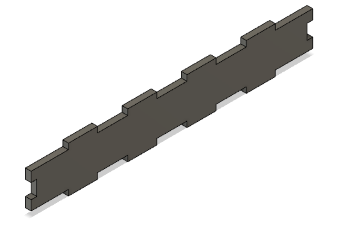
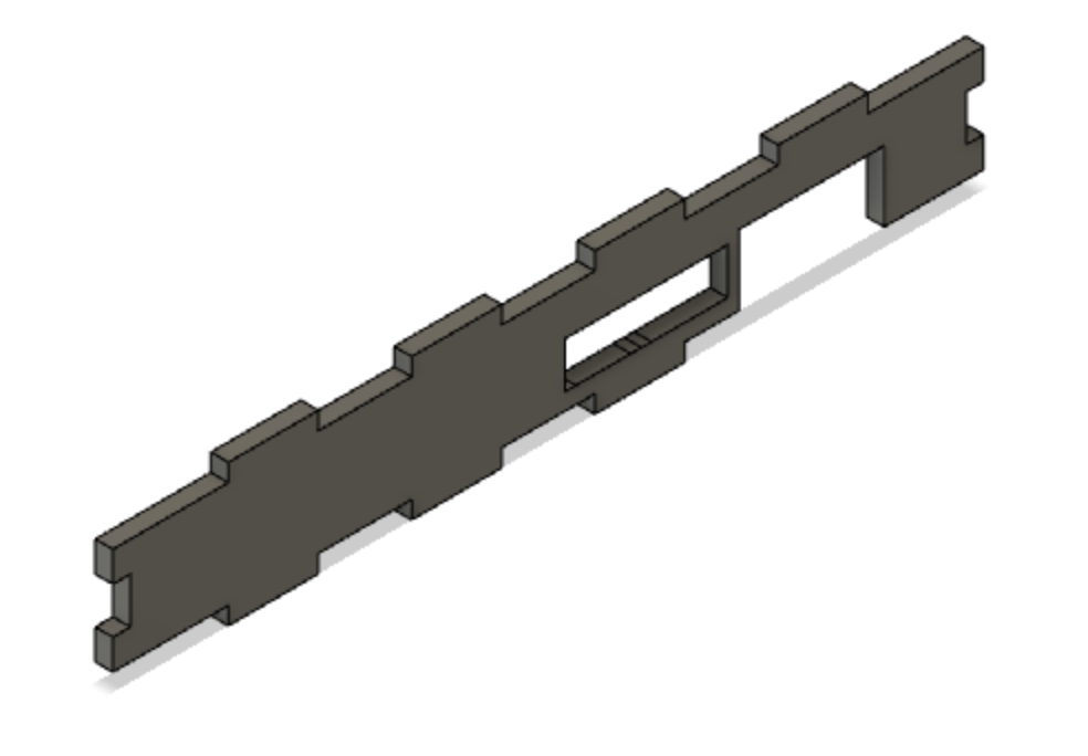
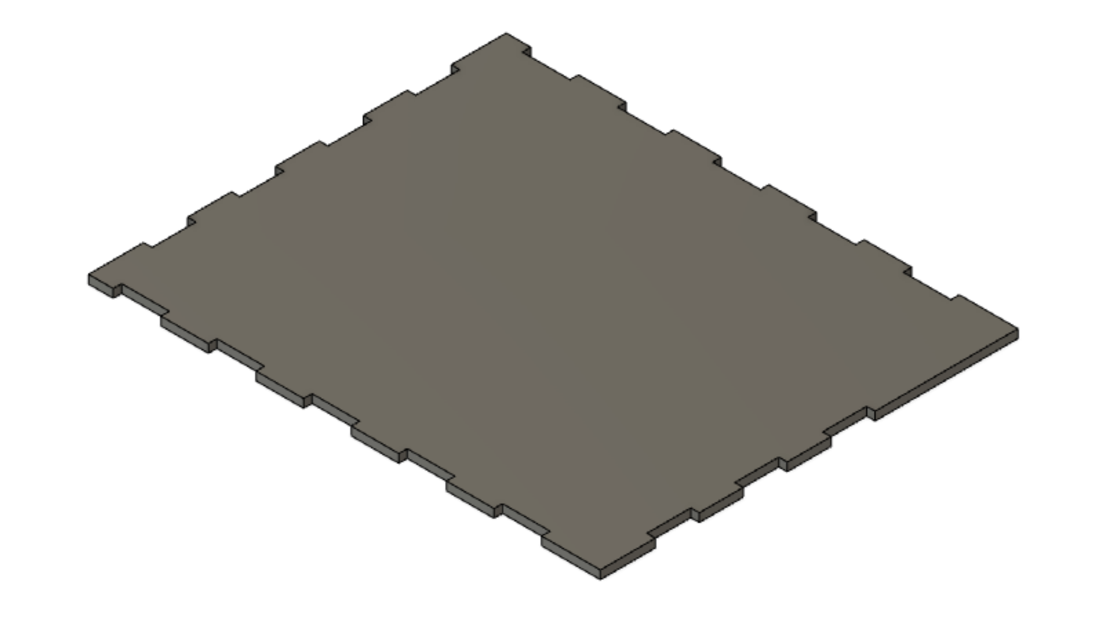
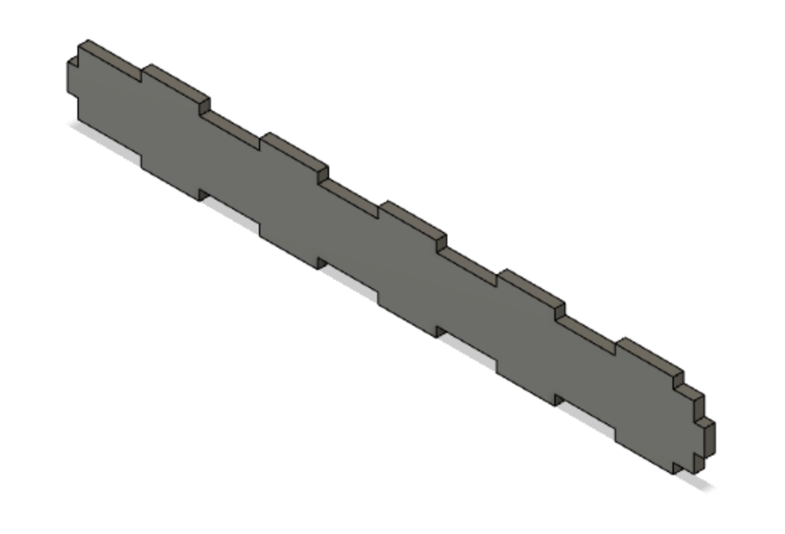
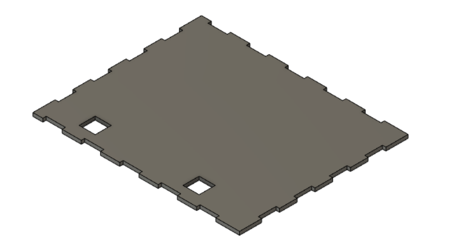
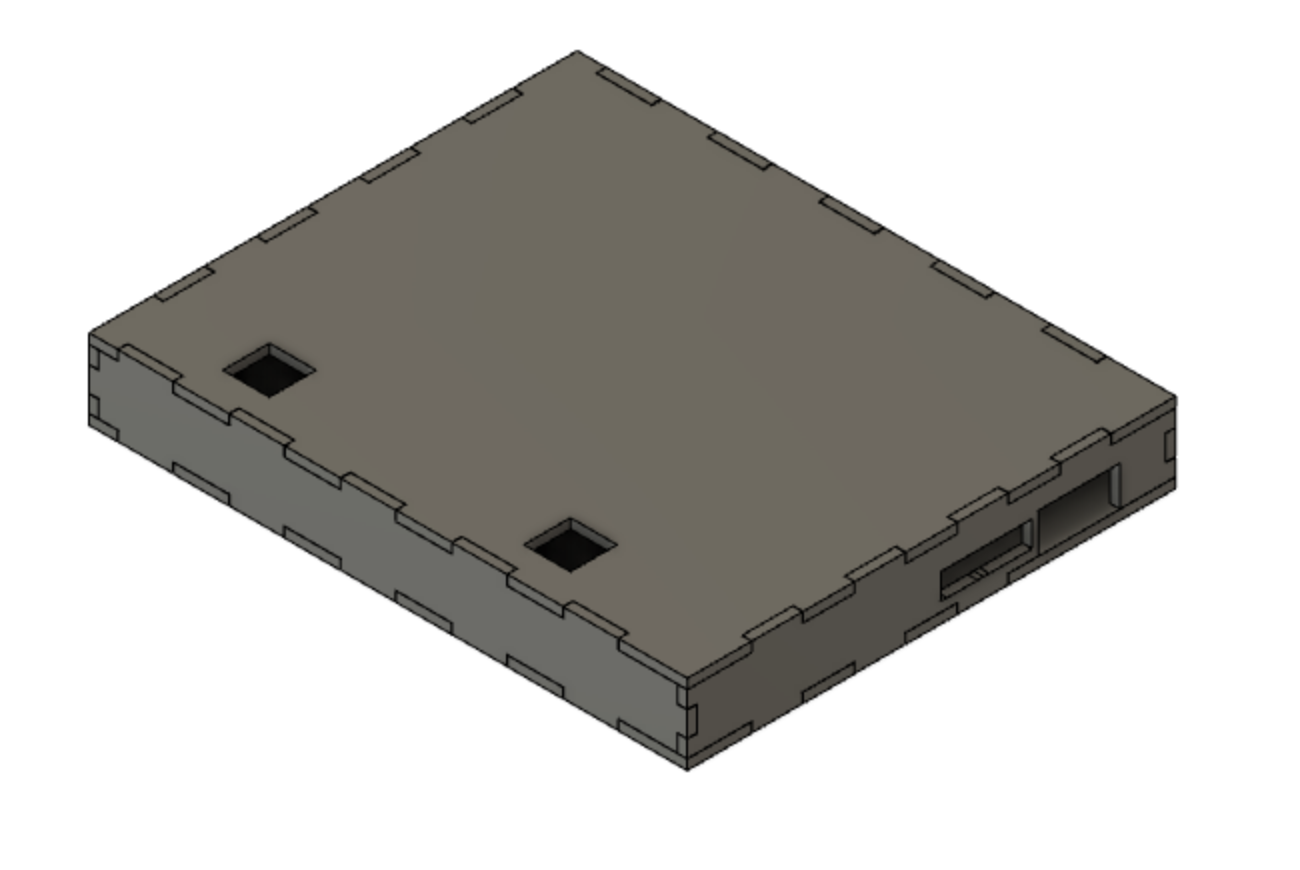
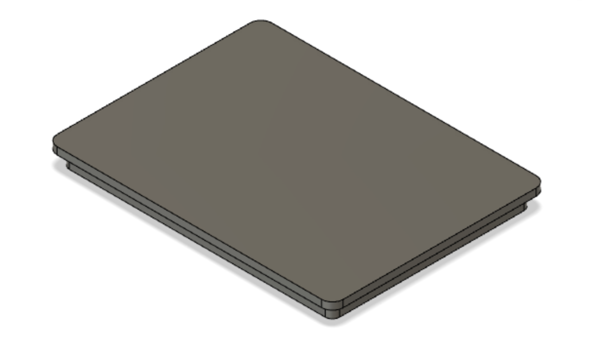
One of Alex's favorite activities is painting and she even has several of her own pieces in her room; however sometimes, she forgets that she has paint on her fingers. As a result, a major design requirement was for the case to be paint-proof, and easily cleanable. Taking this into account, we thought acrylic would be the best material to use for the case. Acrylic is a clear, smooth, lightweight material, that is robust enough to handle paint, water, and other external fluids and variables. To approach this design challenge, we first used CAD to model the design and create the various pieces. There are 6 pieces total: the front, back, top, bottom, left, and right faces. Each piece has extrusions and cuts so that when they are put together, they fit together like puzzle pieces. Within this project, are .stl files of the CAD models as well as annotated drawings. Below are some examples of the pieces that were modeled, the drawings that were created and the final image shows the modeled final assembly of the case.
As you can see from the assembled view in the pictures, the pieces fit snuggly together; however, the friction from these parts is not enough to hold the pieces together. Acrylic is smooth and thus the coefficient of friction between the pieces cannot hold them together alone. As a result, we used acrylic cement to chemically bond the acrylic segments together.
Creating the case with Laser Cutter:
1. Download the .stl files or drawings attached to this project
2. Adjust the parameters to make it custom to your needs; make sure you take into account the thickness of the laser when designing
3. Download the model into the necessary format; I transferred the face of the piece I wanted to cut into a dxf file. Both Solidworks and Fusion can do this
4. Put the acrylic into the laser cutter
5. Set where the laser cutter should cut on the acrylic and begin
6. Once all the pieces are set, put acrylic cement at the joining segments of the faces; make sure you leave the top face off so you can eventually place the monitor in.
7. Please follow all safety precautions when applying the acrylic cement to each side; it is an extremely hazardous solvent.
8. Attach the standoffs that come with the monitor to the four mounting holes on each corner of the monitor.
9. Using 3 miniature packets of sugru, divide the sugru into four balls, and place in the inside corner of each case.
10. Place the monitor into the case, sliding the standoffs into the sugru to secure the monitor to the inside of the case. Be sure to align all of the screen's ports to the respective acrylic cut-outs.
11. Use your fingers to smooth out and press the sugru into the corners. See the resulting image below.
10. Apply the last face and secure it with acrylic cement when the project is finished. To help with finger-prints, apply a standard anti-glare tablet protective film to the top of the acrylic.
Note: the 14mm x 14mm squares cut into the lid should allow standard cherry-MX switches to snap securely into the top, but feel free to use adhesive to secure permanently. Keeping the side of the case with the port-cutouts unattached until the end of the project makes installation of the switches' wires more convenient as well.
For the actual buttons:
We opted to use mechanical keyboard switches, due to the flexibility it would give with creating more accessible buttons. We purchased a set of cheap heavy-actuation force switches, with standard cherry MX stems. For earlier prototypes, we tested various keycap sizes found on a standard mechanical keyboard with Alex to determine what size key she would prefer for the buttons.
Raspberry Pi Basket
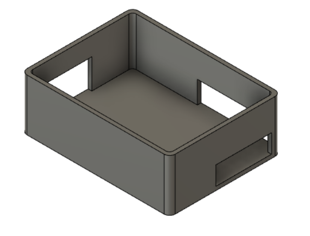
A basket that holds the raspberry pi is also implemented. This, unlike the monitor case, is made out of 3D printed material. We decided to make this using a 3D printer because ease of cleaning is not overly important for this piece, as it will be attached to the back of Alex's wheelchair via command strips. Although aesthetics are not overly important, 3D printing will still result in a clean, smooth finish. 3D printing is also easier when it comes to making light, robust, casings compared to laser cutting. The case is a minimalist design, minimizing the amount of material needed but still keeping the core function of the device. Gaps in the case were cut to provide space for the wire to plug into the raspberry pi. Below is a picture of the lid and the case.
We wanted to place a case on the camera as well because of Alex's activities throughout the Boston Home. The camera we are using is a common camera that is used for raspberry pis. We found a camera stand from MicroCenter that we rigged to be able to be placed onto Alex's wheelchair. Below is a picture of the piece.
The Monitor MountThroughout the Boston Home, you see various monitor mounts on the residents' wheelchairs. We used a very similar monitor mount and modified it to fit our needs. We created bumpers on the left, bottom, and right side of the mount that would hold our case in place. The bumpers were 3D printed. We then drilled a small slot on the bottom left bumper so that we could run wires through it.
PoweringA Raspberry Pi is incapable of going into sleep-mode, resulting in unfavorable power consumption and the inability to turn on a Raspberry Pi outside of re-connecting the power cable. We use the Sleepy Pi 2 shield to combat this, a power conservation shield that has an Arduino-compatible micro-controller and on-board voltage regulators for added safety.
The Sleepy Pi 2 can be powered in different ways as described here, but we opted to use the Micro-USB port, connecting to the client's wheelchair battery via a USB-A port. Powering the Sleepy Pi powers the connected Raspberry Pi; please follow the manufacturer's instructions, particularly the warnings regarding using rechargeable battery packs.
Be sure to follow all of the sleepy pi 2 setup instructions, including running the appropriate .sh setup files.
Note: In our case, the Sleepy Pi 2 malfunctioned, so we simply power the Raspberry Pi through its usual Micro-USB socket.
Putting It All TogetherThe HDMI cable connects from the Raspberry Pi to the screen, with one Micro-USB cable connected to the Raspberry Pi to power the screen via the appropriate Micro-USB slot.
Powering the Raspberry Pi itself is discussed above, with the power source being a USB socket connected to the wheelchair battery, which we requested the client's home's staff to install.
The Raspberry Pi is connected to the camera module, and the module itself is placed in the camera mount and its angle is adjusted to the user's preference.
We used Command velcro strips to attach the Raspberry Pi case to the back of the wheelchair, being sure that the flex ribbon connecting the camera module was sufficiently long enough.
Previous Iterations and TestsFirst Prototype: Sensors
For our first prototype, an Arduino Uno was connected to two HC-SR04 Ultrasonic Range Sensors. The range sensors were connected to the Arduino using multiple male to female jumper wires. Each range sensor had a connection to ground, 5V, and two of the Arduino’s digital pins. To connect multiple sensors to the 5V pin we used a breadboard. The Arduino was also connected to a speaker with a resistor in series, this resistor also being placed on the breadboard. The Arduino was loaded with code that would command the ultrasonic range sensors to send out a pulse, then would receive a reflection of that pulse off of an object. Based on how long that reflection took to be received, the Arduino calculates how far away the object is. For our tests we set the Arduino to play a beeping sound if something enters a range of 8 inches, but stop beeping if the distance between the sensor and the object is nondecreasing. That way if Alex stops or moves away from an object, the beeping stops. The Arduino was powered by a USB power bank.
Second Prototype: Mirror and Backup Camera
In one of our visits to the Boston Home, Alex mentioned that she wanted a rear-view mirror for her wheelchair in order to safely back out of the narrow alleyway by her bed, so we developed a second set of prototypes, inspired by two methods used for drivers to back up their cars. The first part was a mechanical solution modeling a side mirror, while the second represented a backup camera, a safety feature widely used by vehicles starting in the 2000s. Alex has driven a car before, so she has had experience using side-view mirrors, but she has never driven in a car that uses a backup camera.
Our side mirror for Alex’s wheelchair consisted of a small compact mirror connected to a selfie-stick. We used masking tape and the selfie-stick phone grip to keep the mirror on the stick, and then we used more masking tape to attach the stick to Alex’s wheelchair. One major advantage of using the selfie-stick was that it was adjustable, so we were able to fit the stick to the appropriate height for Alex. This is an important consideration since Alex may become slightly shorter as she grows older, and we’d like our solution to adjust to Alex’s needs in the future. Using this side-view mirror, Alex was able to see the space surrounding her back wheel on one side (we tested the right side). However, one of the disadvantages of the mirror, which Julie, one of the assistants at the Boston Home responsible for Alex, also noticed, was that it makes Alex’s wheelchair “wider”, which may result in collisions of the mirror with other Boston Home wheelchair users.
Our back-up camera used two smartphones connected with Google Duo, the video calling feature for Android phones. One phone was placed in front of Alex, while the other phone was placed behind her wheelchair. We also attempted two angles for the phone behind her wheelchair. In the first iteration, we taped the camera directly to the back of the wheelchair to face perpendicularly to the floor, capturing the scene behind her wheelchair. In the second iteration, we attached the phone to the selfie-stick, which we used to angle the camera towards the floor so that Alex would be able to see her two back wheels and the area of the floor surrounding them.
Third Prototype: Backup Camera
Our third prototype was a more advanced version of the backup camera. This involved attaching a raspberry pi camera and a 7in HDMI monitor to the raspberry pi. The camera was placed at an optimal angle on the back of her wheelchair and the monitor was held by a teammate in front of her so that she could see the camera feed. As well on the camera feed was an overlay image of two lines that showed the future path of her wheelchair if she continued going straight.
Results from the Prototypes
In our first tests, we had Alex back up into After testing the first prototype, Alex stated that she really enjoyed having the sensors and the sound feedback and would like if we implemented them in the final design despite the sensor feedback not yielding the best results in terms of wheelchair avoidance. In response, we are trying to connect the sensors to the raspberry pi and implement them to our final design.
The second trial of prototypes revealed to be very useful. We tested our second prototypes during our visit to Alex at the Boston Home on October 25. To safely model the problem alley next to her bed, we laid two lines of blue masking tape about 30 inches apart on the floor in her room. We then asked Alex to drive her wheelchair to the start of the tape and back up through the lane, first without any of our prototypes as a control, and then for each model that we wanted Alex to try. We took a video for each of her attempts, observing whether she crossed the tape and how steadily she stayed in the lines of tape. Then we followed up with some questions about how confident and safe she felt while backing up.
We found that for the side mirror, she seemed to be focused on just her right side, since that was where the mirror was placed. She seemed to like the backup camera model, and navigated her wheelchair more steadily and centered in the lane with the second camera angle (facing her two back wheels).
From the results and secondary e-mail feedback affirming her preferences, we decided to use the backup camera solution as our main solution to the project.
The third prototype tests involved similar tests to the tests described above. We laid out two pieces of tape that were the width of the tight space in her bedroom and asked her to back up from an angle and turn into the two lines and back up straight while staying within the lines. Alex performed remarkably and stayed fairly center between the lines. She stated that she really like the backup camera and believed it was really useful. This solidified the idea that this will be our final product.
CustomizationThere is a static png overlay on the camera stream, delineating the trajectory of the client's wheelchair when backing up. Based on the specifications of the wheelchair, the overlay's guidelines can be edited in Photoshop or Gimp. We used Photoshop, but a similar file has been created for use with Gimp, which is free to install. This works with the 1024x600 resolution of our screen.
The layers have been annotated as such: the Computer Margins layer is what appears on either side of the stream, hiding the underlying desktop. The middle layer is the Camera Field of View, and the Overlay layer contains what will be on overlaid on the camera stream.
Please only edit the Overlay or Computer Margins layer, being sure to make the Camera Field of View layer invisible by clicking on the eye-symbol before exporting as a png.
For the tablet case:
Although we used acrylic, the case can also be created using a 3D printer. We chose not to use 3D printed materials because it would be more expensive, the material is a little more rough than acrylic, takes more time to make, and the bed size of the available printers were not large enough to house some of the pieces (the top and bottom faces of the case). One of the benefits of using 3D printed materials, is that you can usually create a snap fit for pieces to snap into each other, and the friction between the pieces is typically enough to keep them secured together. Epoxy/an adhesive is not necessary but is a good touch for extra security. Even though we did not use a 3D printer, you still can try if you would like.
1. Download the .stl files and drawings
2. Adjust the parameters to make it custom to your needs; make sure you take into account the thickness of the laser when designing
3. Save your models as a .stl or .obj depending on the printer you have
4. Depending on the printer, use a compatible 3D printer software to setup the bed of the printer with your part
5. Adjust the position of your part to minimize the amount of support material needed without destroying the part in the process
6. After the part is printed, take it out and take off the support material.
7. If needed, wash the part and cure it
8. Assemble the pieces together as in the assembly picture
9. Epoxy the pieces if deemed necessary
Future WorkOur client requested some peripherals the second-to-last week of the term, and given our availability, we have provisionally decided to continue working on the project. She requested sensors to cover the front her wheelchair, and "non-auditory alarms, such as vibrations" to alert her when in proximity of something. We have some work from prior iterations that may be applicable to such progress, going forward, but this will likely drastically change how and where our peripherals are wired up on the wheelchair.
The Range Sensor Code
import RPi.GPIO as GPIO
import time
GPIO.setmode(GPIO.BCM)
TRIG = 23
ECHO = 24
print "Distance Measurement In Progress"
GPIO.setup(TRIG,GPIO.OUT)
GPIO.setup(ECHO,GPIO.IN)
GPIO.output(TRIG, False)
print "Waiting For Sensor To Settle"
time.sleep(2)
GPIO.output(TRIG, True)
time.sleep(0.00001)
GPIO.output(TRIG, False)
while GPIO.input(ECHO)==0:
pulse_start = time.time()
while GPIO.input(ECHO)==1:
pulse_end = time.time()
pulse_duration = pulse_end - pulse_start
distance = pulse_duration x 17150
distance = round(distance, 2)
print "Distance:",distance,"cm"
GPIO.cleanup()
1. We set the TRIG pin as an output and the ECHO pin as an input with GPIO.setup.
2. We wait for the sensor to settle with time.sleep(2)
3. Turn the output on the TRIG pin on with GPIO.output(TRIG, True). We keep the output turned on for just 0.0001 seconds, after which we turn the output off again. The TRIG pin on the ultrasonic range sensor triggers the sensor to send out an ultrasonic pulse.
4. We record the start time of this pulse with pulse_start = time.time(), and waits to measure the time it takes for the sensor to receive a reflection of that pulse.
5. When the reflection is received, the sensor will send a signal through the ECHO pin. We record the time this happens with pulse_end = time.time(), and find the total time it took to receive the reflection by subtracting pulse_start from pulse_end.
6. By knowing the speed of sound and the time it took for the sound to reflect off the object, we can do some calculations that simplify to distance = pulse_duration x 17150. That gets us a relatively accurate approximation of the distance away the object is.
For the tablet case:
We are considering changing the enclosure such that only two sides of the monitor are covered in acrylic; the front and the back, with longer stand-offs securing all of the pieces. This is not only for aesthetics, but should prove more robust with regards to circulation for the screen's heat dissipation.
For the buttons:
Based on the peripherals and (number of) sensors, the final functionality of the two buttons will likely change. The current buttons are simply standard mechanical switches that were painted with "ON" and "OFF", as Alex is not familiar with computers or electronic systems, but the final buttons, their design and functionality will likely be different, but will still utilize the Cherry MX switch and stem. We are considering using poured resin (albeit less artistically fine, and with more emphasis on the button's "label") or other mediums to create more aesthetically pleasing final buttons for Alex.
Laser Cut Case: Right Side Face


Comments
Please log in or sign up to comment.