


Hardware components | ||||||
 |
| × | 1 | |||
 |
| × | 1 | |||
| × | 1 | ||||
| × | 2 | ||||
 |
| × | 1 | |||
 |
| × | 1 | |||
 |
| × | 1 | |||
 |
| × | 1 | |||
Software apps and online services | ||||||
 |
| |||||
| ||||||
We’ve developed an interactive, gesture-controlled scale model of the University of Manchester’s Engineering Building, powered by machine learning and embedded systems.
Our model responds to hand gestures in real-time:
Swipe left → left side of the building opens
Swipe right → right side opens
Raise both arms in a T-pose → the entire building rotates
This touchless control system allows users to interact with a physical structure in a completely new way, offering endless possibilities for educational tools, exhibitions, and smart environments.
💡 Why We Built ItWe set out to explore how gesture recognition and embedded machine learning can be used to control physical models. Our goal was to demonstrate how these technologies can be leveraged to create intuitive, immersive experiences where users can engage with models or environments in a more natural, hands-free way.
In many scenarios, traditional interaction methods—like buttons or screens—can be limiting. By incorporating gesture control, we enable users to engage with a system without touching it, adding flexibility and accessibility. This concept has applications in:
Smart architecture: Buildings or spaces that react to human input.
Interactive exhibits: Where users can control models or display systems via simple gestures.
Public spaces: For contactless interaction with technology, ensuring ease of use and accessibility.
⚙️ How It WorksGesture RecognitionThe system uses a Raspberry Pi 5 with a camera to detect gestures in real time. A TensorFlow Lite model is employed for efficient gesture classification. We trained the model to recognize specific hand gestures:
Swipe left: Initiates opening of the left side of the model.
Swipe right: Triggers the right side to open.
T-pose: Commands the model to rotate around its central axis.
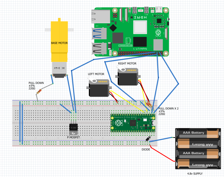
Actuation (Raspberry Pi Pico)The Raspberry Pi Pico acts as the real-time controller for the servo motors that physically manipulate the model:
Two servo motors control the opening of the left and right sides of the building.
One central servo motor controls the rotation of the model when the T-pose gesture is detected.
This division of labor between the Pi 5 (for gesture detection) and the Pico (for real-time motor control) ensures the system operates efficiently with minimal latency.
🛠️ Tec h StackRaspberry Pi 5:
Runs the gesture detection model using TensorFlow Lite for efficient, edge-based machine learning inference
Uses OpenCV to process camera input and detect the gestures.
TensorFlow Lite: A lightweight version of TensorFlow, optimized for edge devices like the Raspberry Pi. It enables efficient real-time gesture recognition.
Finite State Machine: Tracks user gestures and interprets the sequence of movements to determine the appropriate model response. The FSM ensures actions only occur when the correct gesture is performed.
Raspberry Pi Pico: A microcontroller that interfaces with the servo motors for real-time control of the model’s movement.
Servo Motors: The physical actuators that control the opening of the model and its rotation. These are powered and controlled via the Raspberry Pi Pico.
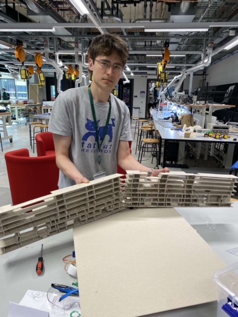
Custom-Designed Model: The UoM Engineering Building model was handcrafted using foamboard and 3D-printed parts to create a functional representation of the structure. The model was designed with three key moving components:
Left side opening
Right side opening
Central rotation mechanism
🧠 Wha t We LearnedReal-time machine learning on embedded devices: Using the Raspberry Pi 5 for gesture recognition in real-time, paired with TensorFlow Lite, proved to be both efficient and responsive.
Servo control: Managing real-time actuation with the Raspberry Pi Pico and coordinating the servo movements was challenging but demonstrated the power of using low-cost hardware to create interactive models.
Gesture sensitivity and calibration: Fine-tuning the gesture detection required iterative testing to balance accuracy and responsiveness in diverse lighting conditions and environments.
🎯 Pot ential ApplicationsProject AURA shows the potential of gesture-based control systems for applications in various fields:
Interactive Exhibitions: Museums, science centers, and educational settings could use gesture-controlled models to engage visitors and demonstrate complex systems in a hands-on way.
Smart Buildings: This concept could evolve into a system where users control architectural elements — like blinds, windows, or even rooms — simply by gesture.
Public Spaces: In environments like malls, public transport, or smart cities, users could interact with digital displays, models, or even physical structures through gestures, reducing the need for physical touchpoints.
🌟 The TakeawayProject AURA demonstrates that machine learning and embedded systems can be integrated seamlessly to create a hands-free, interactive experience. By using simple gestures to control a physical model, we provide a glimpse into the future of intuitive, responsive architecture.
We believe this project is just the beginning, and with further development, it could expand into applications in smart cities, accessible technology, and educational tools.


Comments