This hands on lab demonstrates how to read a light sensor (or any other analog sensor) using the Devices for Microsoft IoT Core library and how to show that sensor data on a screen. We will cover analog sensors, how to leverage an ADC chip and using XAML to build a User Interface for our IoT project.
We'll start by creating a new Windows Universal project in Visual Studio 2015. We'll use the Blank App template and call our application LightReader.
At this point we have an application that can run anywhere Windows Universal apps run. This includes phones, tablets and eventually HoloLens and XBOX One.
Reference IoT ExtensionsNext we'll add a reference to Windows IoT Extensions for the UWP, which gives us access to the GPIO pins on our microcontroller. To do this, right-click on the References folder inside our project and choose Add Reference… In the window that pops up expand the Windows Universal branch on the left and select Extensions. Then, check the box next to Windows IoT Extensions for the UWP on the right and click OK to close the dialog.
Next we'll add a reference to the Devices for Microsoft IoT Core library. This library provides easy access to sensors, displays and other hardware connected to our device. To do this, right-click on the References folder inside the project and choose Manage NuGet Packages. In the window that pops make sure the Include prerelease checkbox is checked and type Microsoft.IoT.Devices in the search box.
Select Microsoft.IoT.Devices on the left-hand side and click the Install button on the right.
Connecting the ADCNow it's time to connect the ADC0832 Analog to Digital Converter chip. We need to connect the following pins (left side is ADC0832, right side is Raspberry Pi):
- CS -> GPIO 18
- GND -> GND
- DO -> GPIO 24
- DI -> GPIO 24 (or just connect DO and DI together)
- CLK -> GPIO 23
- VCC -> 3.3V
Below are the the pinouts of the ADC0832 and Raspberry Pi respectively:
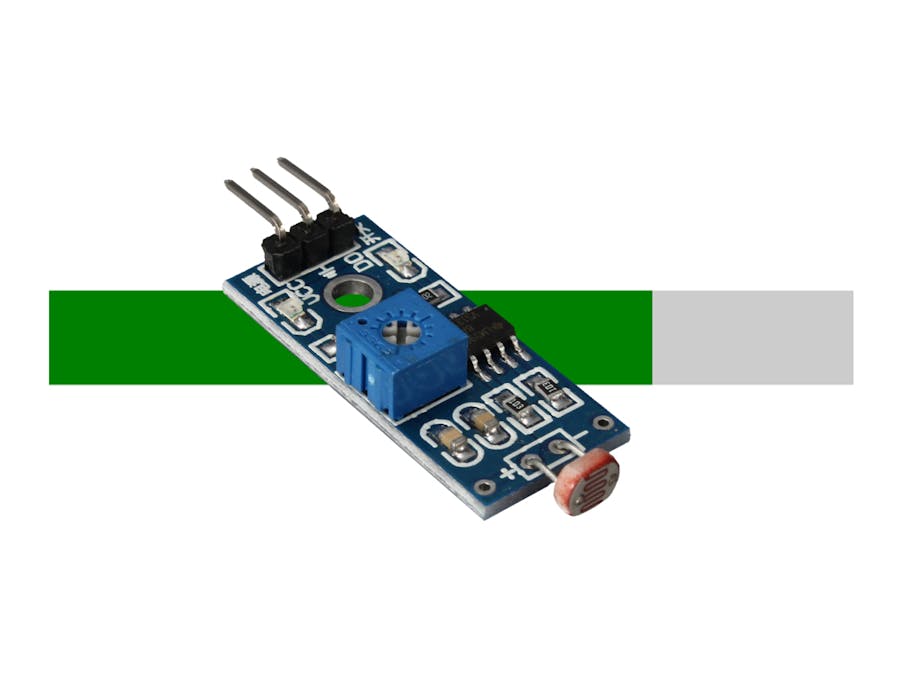
Next let's connect the Photoresistor / Light Sensor (or any analog sensor) to the ADC0832. We need to connect the following pins (left side is the Light Sensor, right side is ADC0832):
- Signal -> CH0
- VCC -> VCC
- GND -> GND
Below are the the pinouts of the Light Sensor:
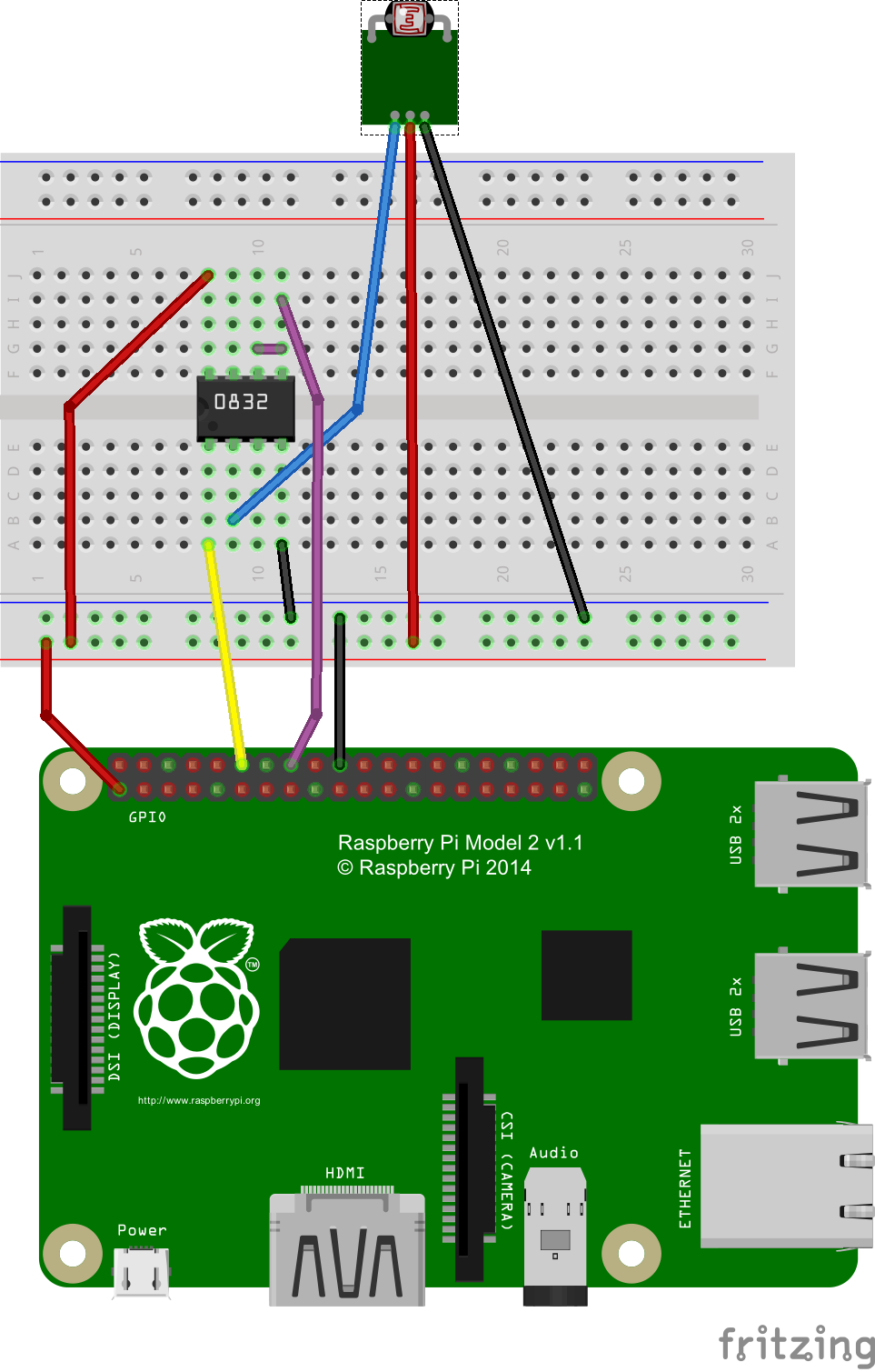
And finally, here is the full breadboard wiring diagram so you can check your work:
The Devices for Microsoft IoT library (and the underlying IoT Core) provide two ways of reading analog sensors: Value and Ratio.
Value is the actual value returned by the ADC chip. The range of numbers returned by the Value property depend on the sensor and the ADC chip. For example, an 8-bit ADC has a range of 0 - 255 while a 12-bit ADC has a much wider range of 0 - 4,095. Some ADCs can provide 24 bits of resolution, resulting in a significantly higher range of 0 - 16,777,215! But keep in mind that every sensor is different, and most sensors don't use the full range of values supported by the ADC.
Ratio on the other hand takes into account the ADC range and always returns a normalized reading between 0.0 and 1.0. For all practical purposes, Ratio can be thought of as a percentage of the possible sensor values. But keep in mind that because most sensors don't use the full range of the ADC you may never see a reading of 0% or 100%.
User InterfaceNow it's time to build an interface to see the output of our sensor.In the Solution Explorer window, double-click on MainPage.xaml.
Inside the main
tag we want to add a ProgressBar that we can use to display the sensor reading. The ProgressBar will have a name ("LightProgress"), a Minimum value of 0 and a Maximum value of 1 because those are the range of values we can expect when we read the Ratio property. We'll set a fixed Height but we wont specify a Width which means it will expand to fill the screen horizontally. Finally, we'll add a Margin so there will at least be some padding between the bar and the sides of the screen.
Add the following XAML inside the main tag:
The complete XAML should look like this when you're done:
Now let's write some code!
In the Solution Explorer window, expand MainPage.xaml and double-click on MainPage.xaml.cs.
Before we can do anything else we need to import some namespaces from the libraries we referenced above. These namespaces give us access to things like ADC and sensors. We'll also import Windows.UI so we have access to colors and other drawing resources.
At the very top of the file but after the other using statements, add the following lines:
using Microsoft.IoT.DeviceCore.Adc;
using Microsoft.IoT.Devices.Adc;
using Microsoft.IoT.DeviceCore.Sensors;
using Microsoft.IoT.Devices.Sensors;
using Windows.Devices.Gpio;
using Windows.UI;
NOTE: Don't worry too much about memorizing namespaces. If you forget them later on Visual Studio will show red squiggly lines under your code. When you right-click on those squiggly lines, Visual Studio will walk you through adding the right using statements for whatever you're trying to do.
Wait for the UI to LoadWe don't want to start reading the sensor until our UI has finished loading. The easiest way to do that is to wait for the Loaded event to happen. In the constructor, right after the call to this.InitializeComponent(); add the following code:
this.Loaded += MainPage_Loaded;
And after the constructor, add the following handler for the loaded event:
private async void MainPage_Loaded(object sender, RoutedEventArgs e)
{

}
We'll put some code in this handler in just a moment, but let's pause for a moment to talk about ADC support in Windows IoT Core.
ADC Support in IoT CoreWindows IoT Core includes several ADC related classes out of the box, but because every microcontroller is different and not every board supports ADC, the Windows team couldn't provide a full implementation of ADC in the same way they did for GPIO. Instead, they built a model where providers for different ADC chips could be "plugged in" to the system and from that point onward the code would work the same regardless of the device it's running on.
The Devices for Microsoft IoT library includes full provider implementations for multiple ADC chips (at the time of writing it supports the ADC0832 and MCP3208 with more on the way). The library also makes it easy to support more than one ADC chip in the same project. This is accomplished through a new class called the AdcProviderManager.
Initialize the ADC ChipWe need to initialize our ADC0832 chip and for that we need GPIO. We're going to use the AdcProviderManager mentioned above and we'll add our ADC to it. Finally we'll use the manager to give us back an AdcController that we can use for the rest of our code. It's important to note that the AdcController class is the same no matter what ADC chip we use, so our code won't have to change even if our hardware does.
Paste the following code into the MainPage_Loaded event handler we created above:
// Start GPIO
var gpioController = GpioController.GetDefault();

// Create ADC manager
var adcManager = new AdcProviderManager();

// Add ADC chips
adcManager.Providers.Add(
    new ADC0832()
    {
        ChipSelectPin = gpioController.OpenPin(18),
        ClockPin = gpioController.OpenPin(23),
        DataPin = gpioController.OpenPin(24),
    });


// Get the well-known AdcController class back
var adcControllers = await adcManager.GetControllersAsync();
Now that we've got access to ADC it's time to create the light sensor. Our sensor is connected to Channel 0 and we only have one ADC Controller so we'll use 0 for that too. We'll set the ReportInterval to 250 so our UI updates often, and finally we'll subscribe to the ReadingChanged event.
Below the code we just finished writing above (and still inside the MainPage_Loaded event handler) add the following:
// Create light sensor
var lightSensor = new AnalogSensor()
{
    AdcChannel = adcControllers[0].OpenChannel(0),
    ReportInterval = 250,
};

// Subscribe to events
lightSensor.ReadingChanged += LightSensor_ReadingChanged;
And finally, after the MainPage_Loaded event, add the event handler for ReadingChanged:
private async void LightSensor_ReadingChanged(IAnalogSensor sender, AnalogSensorReadingChangedEventArgs args)
{
}
Here is the completed code for MainPage_Loaded so you can check your work:
We're about to update our UI but let's learn about our Light Sensor first. In a photoresistor, resistance decreases as light increases. But in our Light Sensor the photoresistor is connected to ground. This means that as brightness increases the numbers will actually get smaller!
Update the UIThe first thing we want to do is subtract the Ratio reading from 1. Subtracting the reading from 1 makes it so our value gets higher as the room gets brighter, which is probably what the user expects. Next we'll update the ProgressBar.Value property to match the reading of the sensor, and finally we'll set the Foreground color of the bar to reflect how much light is in the room.
Add the following code to the LightSensor_ReadingChanged event handler:
// Invert
var reading = 1 - args.Reading.Ratio;

// Update UI
await Dispatcher.RunIdleAsync((s) =>
{
    // Value
    LightProgress.Value = reading;

    // Color
    if (reading < .25)
    {
        LightProgress.Foreground = new SolidColorBrush(Colors.Red);
    }
    else if (reading < .75 )
    {
        LightProgress.Foreground = new SolidColorBrush(Colors.Yellow);
    }
    else
    {
        LightProgress.Foreground = new SolidColorBrush(Colors.Green);
    }
});
Pay special attention to the fact that some of this code is wrapped inside a special call to Dispatcher.RunIdleAsync. We need this line of code because all sensors report data on their own thread, but we can only interact with UI controls on the main UI thread. Dispatcher.RunIdleAsync allows us to say "even though this event was started on its own thread, run the following code on the UI thread".
Here's the completed code for the LightSensor_ReadingChanged event handler so you can check your work:
Now it's time to test our solution. At the top of Visual Studio change the architecture to ARM, then click the dropdown next to the green play button that says Device and change it to Remote Machine.
When you do this, a new window will pop up where you can enter the IP address of your Raspberry Pi. Don't forget to change Authentication Mode to None before clicking the Select button to lock in the configuration.
If you ever need to change these settings later you can right-click on the project, choose Properties then switch to the Debug tab.
Once everything is setup correctly, click the green play button that should now say Remote Machine. After a few moments the application will appear on the HDMI monitor. If you place your hand over the light sensor you should see the bar dip and become yellow or red. When remove your hand or shine a flashlight on the sensor you should see the bar jump and become green.
Congratulations on connecting an ADC chip, reading an analog sensor and updating a user interface with the Devices for IoT Core library!
NOTE: A completed version of this lab can be viewed and downloaded here.


Comments
Please log in or sign up to comment.