A cellular connected asset tracker built on the Hologram Dash. Inspired by @benstr-hologram's GPS Asset Tracker, this tutorial takes it a step further by adding a temperature sensor, LEDs for feedback/debugging, and additional power management controls through the Hologram Dash class's deep sleep modes. What you'll have after following this tutorial is a field-ready solution for remote monitoring connected over Hologram's cellular network.
Features- Hourly GPS and Temperature readings sent to the Hologram Cloud
- LEDs for signaling start-up, device state, and activity
- Deep sleep power save through the Hologram Dash's firmware to minimize power consumption
- Battery life indicator and alerts sent to the Hologram cloud
- Ruby on Rails Web App for viewing your readings and device status
- Hologram Cloud webhook for posting JSON messages
- Waterproof enclosure for prolonged field use in the elements
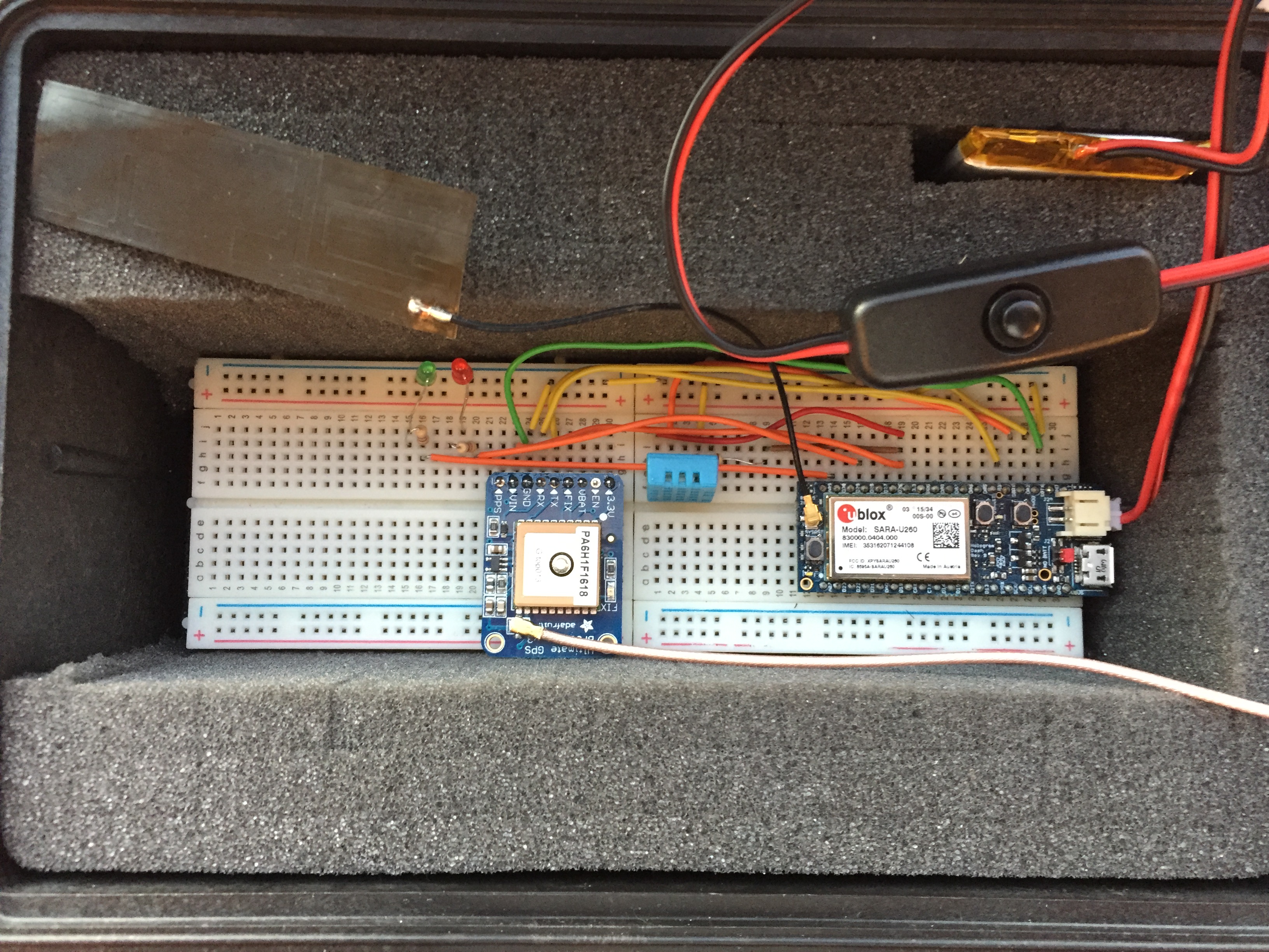
Getting started requires these easy to set-up components arranged in the schematic you'll see below.
Hologram Dash: Hologram's turnkey cellular development board for single line cloud sends! Make sure the red Jumper is moved closer to the battery and microUSB port for proper activation of the Dash’s built-in battery management circuitry
- Adafruit Ultimate GPS Breakout w/ External Antenna: Obtain GPS data simply over the Hologram Dash's UART inputs. Library and reference here: https://learn.adafruit.com/adafruit-ultimate-gps
- DHT22 Temperature Humidity Sensor: Digital Temperature and Humidity sensor connected to the Dash over I2C: https://learn.adafruit.com/dht/using-a-dhtxx-sensor
- LEDs: Driven by the Dash's GPIO pins. Don't forget your pull-down resistors!
- On/Off Switch: Avoid constant removal of the battery connector by installing a SPST switch for simple on/off
- LiPo Battery: 3.7V, 3000maH battery we used with our version was able to provide a few days worth of operation on a full charge. Feel free to plug in an even higher watt-hour battery for longer use.
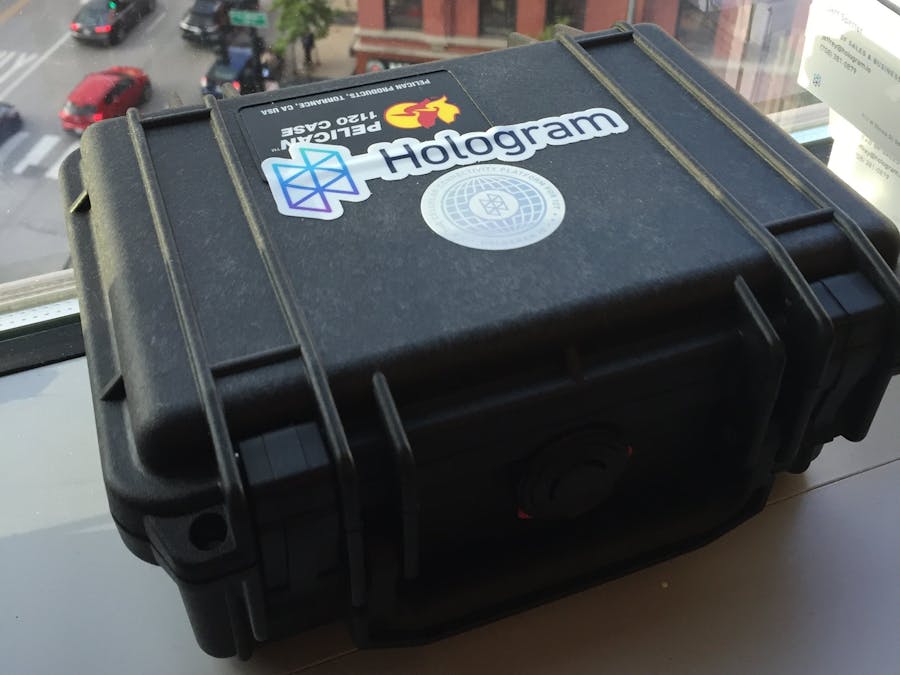
- Pelican 1120 Waterproof Case: Enclosure that fits the breadboards nicely with simple foam cutouts that allow for a snug fit. Case also has built in pressure valve that helps stabilize the temperature inside.
Follow the schematic attached in the picture to get your remote monitoring box wired up and ready for use on your windowsill, backporch, car, or anywhere the Pelican case will fit!
WiringHologram Dash to GPS:
- R12/+3.3V <> Vin
- R02/GND <> GND (Worth checking that GND is set properly with a multimeter, have seen a jumped GND through the breadboard throw off the input voltage before)
- R03/TX0 <> RX
- R05/RX0 <> TX
Hologram Dash to DHT22:
- R02/GND <> GND (Pin 4)
- R12/+3.3V <> Vin (Pin 1)
- R04/D02 <> Sensor Reading (Pin 2) 10K resistor from pin 2 (data) to pin 1 (power)
Green LED:
- R17/D30 <> Resistor <> LED Anode (+) <> LED Cathode (+) <> GND
- Red LED
- R15/D28 <> Resistor <> LED Anode (+) <> LED Cathode (+) <> GND
Connecting a Hologram Dash and SIM to the Hologram Cloud is simple through the dashboard. You can reference Hologram’s quickstart documentation here to see how to get a SIM activated and your Dash programmed here: https://hologram.io/docs/guides-tutorials/getting-started/quick-start-guide/
Hologram GitHub sketch link here: https://github.com/rdotlee/Hologram-Dash-GPS-Temperature-Monitor
GPS Fix and Data Send Intervals:
Getting a GPS fix can be tricky depending on where the device is located and outdoor conditions. Therefore, the code has logic and counters in place so the device still sends back data about every hour as a heartbeat between deep sleep cycles, regardless of whether a GPS fix is locked in by the GPS module. This provides feedback that the Dash is still operational and a cell signal is available. The temperature, humidity, and battery life are also captured as additional diagnostics each hour. These counters and thresholds are all defined as constants in the sketch and can be tuned based on the interval and minimum time for GPS fix seeking you wish to setup for your device. Here’s a walkthrough of the values in the GitHub sketch:
- GPS_SERIAL_SEND_TIME 30000 // The interval the device prints out the current GPS fix status, lat/long, and DHT sensor readings to serial output in milliseconds
- GPS_CLOUD_SEND_TIME 3600000 // The max interval (in this case 1 hour) between cloud message sends from the device
- MIN_FIRST_SEND_TIME 120000 // An assigned minimum time from start-up and waking allowed for the device to send a cloud message. This acts as a buffer between the Dash’s deep sleep waking and the cell modem re-establishing a connection
- DASH_CLOUD_SLEEP_INTERVAL 50 // Minutes for each Dash deep sleep cycle after successfully sending a reading back to the Hologram cloud. Note that the difference between this value and GPS_CLOUD_SEND_TIME is the allowed length of time the GPS module is allowed to poll for satellites and attempt a GPS fix, in this case 10 minutes. This difference can be reduced for battery savings in situations where GPS satellites are easier to connect to from the module.
- DASH_BATTERY_THRESHOLD 10 // Percentage of battery life when the device will send back a data packet regardless of whether a GPS fix is established to signal that the device needs service to be recharged in the field: https://hologram.io/docs/guides-tutorials/getting-started/quick-start-guide/
- Startup - Green LED will flash 10x
- No GPS Fix - Green and Red will alternate 10x
- Dash Cloud Send - Green LED will flash 5x
- Low battery- Red LED will flash 5x
These can of course all be tweaked in the sketch through the flashLED and alternate LED functions:
- Battery Charging
The battery will charge when plugged into a USB power source. It will continue to send signals while charging as well. NOTE: the device must be ON to enable the battery charging circuit.
Device Web App on C9I used the C9 IDE to build a quick web app on Ruby on Rails to view and store your device readings. You can clone my workspace through the repohere: https://github.com/rdotlee/hologram-gps-temp-c9
There are two main objects in this simple web app:
- Devices: These store the device’s Hologram device ID and associated SIM ICCID# which you can find on the Hologram’s Device Dashboard in the screenshot below.
- Device Readings: All associated sensor readings tied to that device.
In addition to all the included CRUD routes, a specific route for receiving data from the Hologram cloud as a JSON data message from the device is included in the GitHub repo which we will connect in the next section.
Hologram Webhook - Putting it all together1. Create a new device in the web app with your Hologram Device ID and SIM # which can be found in the dashboard:
2. In the Hologram device dashboard, create a new webhook that sends each data message as POST to the /create_devicereading_hologram route of the web app. Since the data is already in JSON format, we can put the entire decoded cloud message data through the shortcode <<decdata>> and the device ID through <<deviceid>>:
3. Turn on the device and start monitoring your device out in the field!


Comments
Please log in or sign up to comment.