Hackster is hosting Hackster Holidays, Ep. 7: Livestream & Giveaway Drawing. Watch previous episodes or stream live on Friday!Stream Hackster Holidays, Ep. 7 on Friday!
Kian RobinsonDaniel LiangAsher Lanzone
Published

Project Meta

Enhance your riding aesthetics with a rainbow peripheral which doubles as a pedestrian safety light!

BeginnerFull instructions provided88
Project Meta

Things used in this project

Hardware components

EK-TM4C123GXL TM4C Tiva LaunchPad
Texas Instruments EK-TM4C123GXL TM4C Tiva LaunchPad
×1
Tilt Switch, SPST
Tilt Switch, SPST
×1
Jumper wires (generic)
×11
Photo resistor
Photo resistor
×1
Resistor 1k ohm
Resistor 1k ohm
×2
LED (generic)
LED (generic)
×1
Breadboard (generic)
×1

Software apps and online services

Code Composer Studio
Texas Instruments Code Composer Studio
Energia
Texas Instruments Energia

Story

Read more

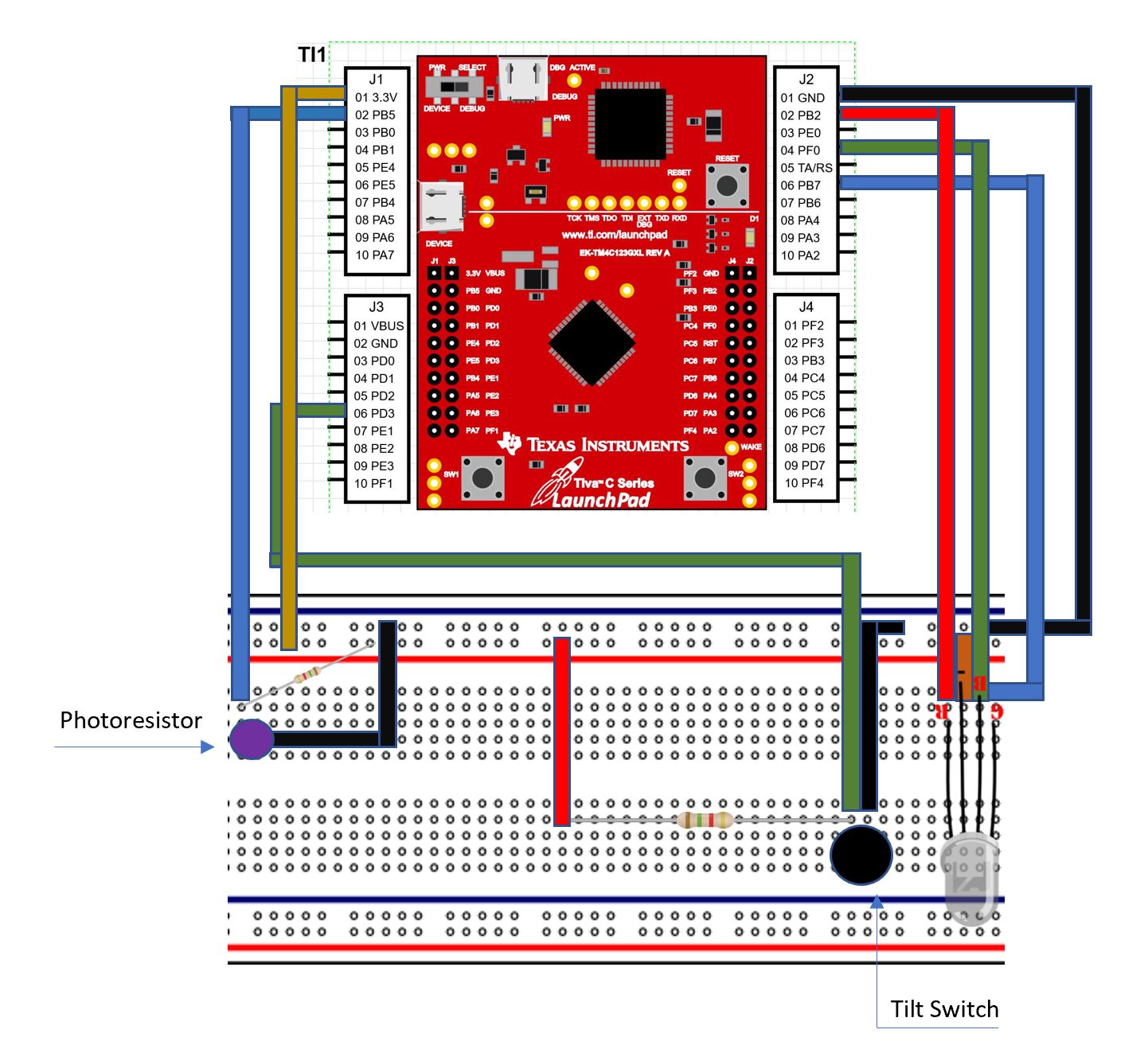
Schematics

Circuit Diagram

Code

main.c

C/C++
/*
 Example 01: Fade RGB LED (PWM)
 Sidekick Basic Kit for TI LaunchPad

 Now we are going to use the special tricolor LED. RGB stands for
 Red, Green, and Blue which are primary colors that can make any
 color we want. This LED can help us make different colors that
 can mean different things.

 We are going to use Pulse Width Modulation to let the LED fade.
 Certain pins on the LaunchPad are PWM capable. In Energia, we call
 this analogWrite() capable. We will want to use those to connect
 to our LED. If you are not sure, check the Energia pin maps on
 the website for your LaunchPad.

 Hardware Required:
 * TI LaunchPad
 * Breadboard BoosterPack
 * Breadboard
 * RGB LED
 * 4x Jumper Wires
 * 3x 330 ohm resistors (optional)

 This example code is in the public domain.
*/

// Connect Anode pin to VCC
// Connect Red to pin 19 which should be PWM capable
// Connect Green to pin with PWM
// Connect Blue to pin with PWM
// You can put a resistor in between to protect your circuit
// but for low power LEDs it's usually okay to drive directly
// from the LaunchPad.

// Let's use #define to rename our pins from numbers to readable variables
// This is good practice when writing code so it is less confusing to read
#define RED 19 // pin 19 is always PWM capable according to LaunchPad standard
#define GREEN 17 // may need to change this for your LaunchPad
#define BLUE 15 // may need to change this for your LaunchPad
#define delayTime 14 // delay between color changes, 10ms by default

// Here we can introduce some global variables. These variables have a type
// (int) and a name. We can use the variables in any function that comes after
// Global variables are useful because we can save the state of a variable to
// use in later operations and functions.
int redVal;
int greenVal;
int blueVal;

/* This is our setup function. We want to set our LED pins as OUTPUT.
 * We can also set them to HIGH at the beginning.
 */
void setup() {
     // We don't have to use pinMode() when using analogWrite() but it doesn't
     // hurt to use it, especially if we want to call digitalWrite() for the
     // same pin in the same sketch.
     pinMode(RED, OUTPUT);
     pinMode(GREEN, OUTPUT);
     pinMode(BLUE, OUTPUT);

     // Test Red
     digitalWrite(RED, LOW);
     digitalWrite(GREEN, HIGH);
     digitalWrite(BLUE, HIGH);
     delay(500);
     // Test Green
     digitalWrite(RED, HIGH);
     digitalWrite(GREEN, LOW);
     digitalWrite(BLUE, HIGH);
     delay(500);
     // Test Blue
     digitalWrite(RED, HIGH);
     digitalWrite(GREEN, HIGH);
     digitalWrite(BLUE, LOW);
     delay(500);
}

/* In the loop function we will fade the brightness of the RGB LED
 * and simultaneously change the colors.
 */
void loop() {
     // We will use a for loop to change the color gradually
     // This will make it fade instead of instantly change
     // We need to go from 0 to 255. You may need to modify
     // your range depending on your LaunchPad to see a smooth
     // result.
     int PWM_RESOLUTION = 255; // this variable will hold our resolution.


     /* Start with full red */
     int redVal = 0; // zero voltage will give us full color
     int greenVal = PWM_RESOLUTION; // max voltage will give us no color
     int blueVal = PWM_RESOLUTION; // max voltage will give us no color
     analogWrite( RED, redVal );
     analogWrite( GREEN, greenVal );
     analogWrite( BLUE, blueVal );

     /* Fade from red to green */
     for( int i = 0 ; i < PWM_RESOLUTION ; i += 1 ){
         greenVal -= 1;
         redVal += 1;
         analogWrite( RED, redVal ); // set the new red value
         analogWrite( GREEN, greenVal ); // set the new green value

         delay( delayTime ); // wait for how long delay time is
     }

     /* Now full green */
     redVal = PWM_RESOLUTION; // max voltage will give us no color
     greenVal = 0; // zero voltage will give us full color
     blueVal = PWM_RESOLUTION; // max voltage will give us no color
     analogWrite( RED, redVal );
     analogWrite( GREEN, greenVal );
     analogWrite( BLUE, blueVal );

     // again we will use the for loop to change the color gradually
     /* Fade from green to blue */
     for( int i = 0 ; i < PWM_RESOLUTION ; i += 1 ){
         blueVal -= 1;
         greenVal += 1;
         analogWrite( BLUE, blueVal ); // set the new blue value
         analogWrite( GREEN, greenVal ); // set the new green value

         delay( delayTime ); // wait for how long delay time is
     }

     /* Now full blue */
     redVal = PWM_RESOLUTION; // max voltage will give us no color
     greenVal = PWM_RESOLUTION; // max voltage will give us no color
     blueVal = 0; // zero voltage will give us full color
     analogWrite( RED, redVal );
     analogWrite( GREEN, greenVal );
     analogWrite( BLUE, blueVal );

     // again we will use the for loop to change the color gradually
     /* Fade from blue to red */
     for( int i = 0 ; i < PWM_RESOLUTION ; i += 1 ){
         redVal -= 1;
         blueVal += 1;
         analogWrite( RED, redVal ); // set the new red value
         analogWrite( BLUE, blueVal ); // set the new blue value

         delay( delayTime ); // wait for how long delay time is
 }
}

Credits

Kian Robinson
1 project • 0 followers
Daniel Liang
1 project • 0 followers
Asher Lanzone
1 project • 0 followers

Comments