A geophone is a magnetic device used to measure the Earth's normal vibrations (some abnormal during events such as earthquakes). These movements are also present when there is a small explosion (commonly used for mining and exploration purposes).
The principle of a geophone is similar to dynamo; the movement of the magnet situated inside a coil cause an induced field and the EMF produces a potential difference (voltage) proportional to the movement. Since, the magnet is spring-loaded and moves along with the small vibrations in the earth, measuring the voltage allows you to measure the movements.
ProtoCentral's OpenPressure is a precision analog signal acquisition platform, that is also very easy to use. It is compatible with Arduino and can be programmed using the standard Arduino IDE. Everything required to drive a sensor, including voltage and current excitation, on-board battery management and a boost DC/DC converter for precision voltage reference make it a highly usable platform for sensing.
For this particular sensor however, an excitation source is not required since the sensor itself produces a voltage (like a dynamo). But the voltage produced is so small that is requires amplification and here's where is the OpenPressure was useful.
Making the connectionsWe used the SM-24 geophone available at Sparkfun as the sensing element. This device is a standard geophone that works similar to the principle described before.
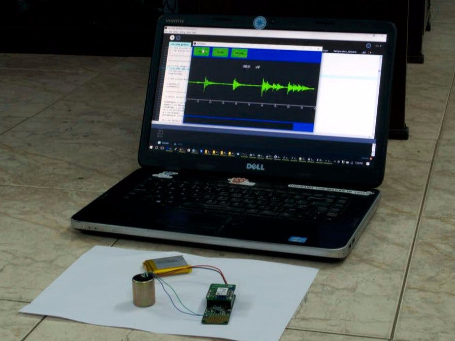
The output leads are directly connected to a differential channel on the OpenPressure board's ADS1220 ADC. Shown below are the connections to be made. The two ends of the geophone are connected to the AIN0 and AIN1 channels, which are differential inputs. In the below picture, you can see wires soldered from the sensor to the board. That's it, the connections are simple.
On the other side of the board, plug in any standard Li-Ion or Li-Polymer battery to the JST connector on the board. The final setup looks like this:
Plug in the OpenPressure board to a computer using a USB micro-B cable and open up the Arduino IDE and this board should show up as an "Arduino Zero bootloader" device. For more information on setup with Arduino, please check the Getting Started Guide here. The version that you see above has a Bluetooth wireless "cap" attached which automatically adds Bluetooth wireless connectivity for easy testing.
The software including the Arduino code as well as the Processing-based IDE for receiving and plotting the data is available in the code repositories given below this article.
Testing and resultsFor actual seismic measurement, the sensor has to be mounted on a rig similar to the one shown below. This then has to be driven into the ground to pick up vibrations.
However, since we couldn't lay our hands on such device, we just tested the functionality by placing the sensor on the ground and measuring vibrations produced by walking , as well as the vibrations produced on the road by passing vehicles. Particularly interesting was how we were able to see small vibrations in the road before the vehicle actually passed by, really open's up a number of ideas. Check out our results in the below video.


_3u05Tpwasz.png?auto=compress%2Cformat&w=40&h=40&fit=fillmax&bg=fff&dpr=2)
Comments
Please log in or sign up to comment.