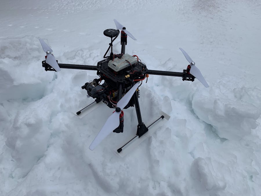
We wanted to learn about quad copter. This challenge is a good opportunity to learn something new.
Goal:For this challenge we decide to make the quad copter easier to fly and provide an eye in the sky to help evaluate the fire.
How to provide the eye in the sky:We added an “Eachine TX03 NTSC Super Mini” camera and design a 3D printed mount/battery holder. Used in conjunction with FPV Goggles this would provide a good setup to evaluate a fire situation.
We designed a pod at the bottom of the quad that would house 7 "Ultrasonic Ranging Module HC-SR04". These sensors in conjunction with the PX4 current
collision prevention software would be a great addition to help control the quad copter.
Using a 3D designed Octagon casing we incorporated 3 sensors in the front, 3 in the back and one at the bottom.
The 5V power is provided by a buck converter directly connected to the battery.
The ultrasonic module control, aggregation of data and I2C communication to the controller is archived using a “Nano Arduino“.
For this initial prototype we used the sf1xx driver code. This code is for a single sensor but by giving only the shortest reading of the 6 peripheral sensors we archive most of our goals.
Since it is winter here and the weather did not cooperate, the final testing was only done on the ground.
It did pass the tests we could do without taking flight:
To prevent the quad copter from sinking in the snow we design skies for the landing gear.
We used an octagon for the housing of the sensors. This gives us 3 sensors in the front and back at 135 degrees.
The range of the sensors is 4 meters. So if we take 2 meters to stop and we make a reading every 300ms the max speed should be:
At the maximum speed allowed we assume we need the same distance to stop.
4 meters detection range / 2 = 2 meters travel speed
2 meters detection time / 300ms max detection delay * 60 sec * 60 minutes / 1000 meters = 24 km/h
Looks ok…
Wiring:Ground:
· Connect all the module grounds and the Arduino ground to the DC-to-DC buck converter ground.
5V Power:
· Connect all the module power and the Arduino power to the DC-to-DC buck converter power.
Module control/reading:
· Connect all the module triggers to the pin D12 of the Arduino.
· Connect each module sensor echo pins to pins D2 to D12 of the Arduino.
Battery to 5V:
· Connect the buck converter to the pole of the battery.
I2C interface from the PX4 to the Arduino:
· Connect the Arduino A4 to the PX4 SDA
· Connect the Arduino A5 to the PX4 SCL
· Connect the Arduino Ground the PX4 Ground
Enable the driver and collision prevention software on the PX4.In QGroundControl set these parameters in the vehicle setup/parameters:
MPC_COLPREV_D to 4.0
SENS_EN_SF1XX to SF10/a
This should enable the SF1XX driver and the collision prevention software.
Reboot the PX4 after that.
This is where we are; we did not test the collision prevention software using this new ultrasonic sensor array in flight.
Conclusion:This was a big job:
- We needed to build the base kit.
- Get the needed certification to fly the quad in Canada.
- Understand the software on the PX4.
- Design and print several 3D parts.
- Design the new ultrasonic sensor software.
We did have fun;-)
A big thanks to the hovergame team.


Comments
Please log in or sign up to comment.