RGB LEDs are widely used in many of the projects with Arduino platform. They work on the basic concept of combination of the basic colors of any shade, that is, red, green and blue. All the colors have these elementary color components in them. Thus, we can make any color we want using a RGB LED.
In the market, there are two types of RGB LEDs - common cathode and common anode LEDs. People (especially beginners) often get confused as common cathode ones are easy to use, but the common anode one behaves differently, even if they are from the same brand and look the same externally on same Arduino sketch.
What is RGB LED?These LEDs have three tiny LEDs of 3 primary colors (red, green and blue) where a terminal is common for all. Some have common positive terminal (anode) and some have common negative terminal (cathode). When different voltage is applied to different LEDs, they make a mixture and produce several thousands of colors.
Circuit diagram of CC and CA RGB LEDs.
Analog to Digital Conversion and vice-versaFor the analog voltages from 0 V to 5V, values (0 - 255) are entered as digital values.
It is done by adhering to the formula and relationship:
The formula can be evaluated using the equation of line with two points on graph.
Digital Value = 51 x Analog Voltage
For example, if analog voltage of 2 V is required, then digital value to be entered is 2 times 51 which is equal to 102.
Using Common Cathode (CC) RGB LED with ArduinoSetting up the circuit:
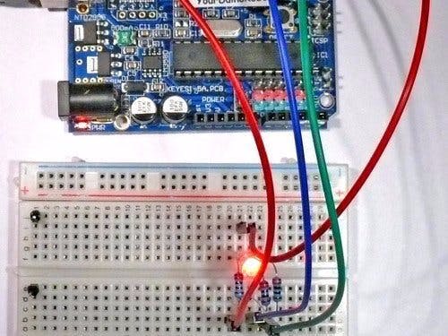
Hooking up the components is easy.
- Plug the CC LED into the breadboard.
- Take the common anode terminaland connect it with the GND pin in the Arduino.
- Connect each of the led color terminals (red, green & blue) with the digital pins in Arduino with the 221 ohm resistors in series with each one of them.
Upload the sketch and open the Serial Monitor to enter the values.
Common Cathode circuit are easy to play with, and their coding is simple. The more the value is, the more the intensity will be of the corresponding color. This is called Current Sourcing.
Working of CC RGB LED:
while(Serial.available()==0){
   }
   redBrightness = Serial.parseInt(); //Stores value in variable
   Serial.println(redBrightness);    //prints value on serial monitor
analogWrite(red, redBrightness);     //sends analog signals to red LED
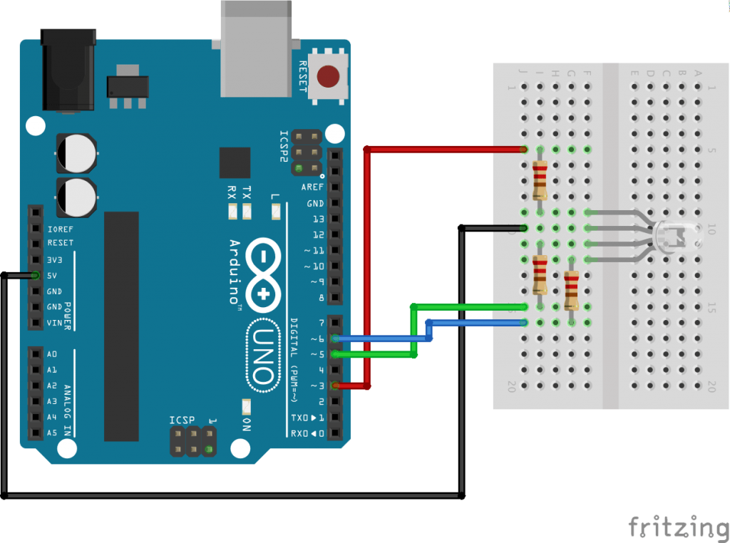
Setting up the circuit:
- Plug the LED in the breadboard.
- Connect common anode of LED to 5V pin of Arduino (In common cathode, we connected it to GND pin).
- Connect each of the led color terminal(red, green & blue) with the digital pins in Arduino with the 221 ohm resistors in series with each one of them.
For this, code doesn't do the more the value, the more is the intensity of the corresponding color. These LEDs work on the principle of Current Sinking.
Working of CC RGB LED:
while(Serial.available()==0){
   }
   blueBrightness = 255 - Serial.parseInt();
/**
    Here, the value is taken and the difference between value and 255(peak value) is stored in the variable.
**/

   Serial.println(blueBrightness);    //Prints value on the serial monitor
   Serial.println("   ");
analogWrite(blue, blueBrightness);    //sends analog signals to blue LED
For example: We want to supply 3 V to blue LED. Using formula, 3 x 51 = 153!
- 153 is entered in serial monitor, the difference is 255 - 153 = 102.
- Thus, the value of 'blueBrightness' is 102. Using the formula, 102 gets converted into analog voltage of 2 V.
- Now, 5 V at anode is opposed by 2 V in opposite direction and the net voltage is taken as:
- Net voltage = V1 + V2
- = 5 + (-2) [2 V is taken as -2 V because of opposite direction w.r.t. 5 V]
- = 5 - 2
- = 3
Thus, at the end, the net voltage supplied is 3 V as it was required.
NoteAs of 1/2010, the pins in the datasheet are correctly labeled. Pin 3 is Green and Pin 4 is Blue. Those purchased prior to then will have Blue on Pin 3 and Green on Pin 4.
GOOD LUCK and try this!


Comments
Please log in or sign up to comment.