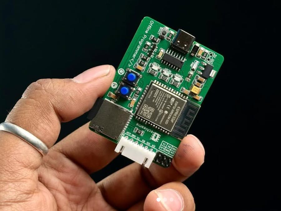
The idea for the ESP Offline Programmer was born out of frustration during a critical project deployment. Imagine being on-site, ready to flash firmware onto multiple ESP32 devices, only to be met with delays from a slow laptop, outdated libraries causing compilation errors, and the ever-looming possibility of connectivity issues.
The process of flashing firmware became a bottleneck, slowing down the entire operation. That’s when the thought struck: “Why rely on a computer when a standalone device could handle this task?” A compact, portable tool that could store firmware and flash it to ESP modules directly—no compiling, no updates, no hassles.
This need was not just personal. Makers, developers, and technicians worldwide faced the same challenges. Whether in the lab, on the factory floor, or in remote locations, the dependency on a computer for programming ESP chips often led to inefficiencies. The ESP Offline Programmer was envisioned as a solution to address these pain points, offering speed, reliability, and simplicity.
To build the ESP Offline Programmer, you will need:
- ESP32 Module
- SD Card Module
- Push Buttons (for programming and reset)
- LEDs (for status indication)
- PCB
- MemoryCard
- Component: CH340C
- Purpose: Converts USB signals to TTL-level UART signals to communicate with the ESP32 or ESP8266 module.
Connections:
- TX and RX pins for serial communication.
- DTR and RTS pins are used for automatic bootloading (control GPIO0 and EN pins of ESP32/ESP8266).
- Connections:TX and RX pins for serial communication.DTR and RTS pins are used for automatic bootloading (control GPIO0 and EN pins of ESP32/ESP8266).
- Power: Receives 5V input through a USB Type-C port.
- Component: LM1117-3.3
- Purpose: Converts the 5V input to 3.3V required by the ESP32 and SD card.
Additional Components:
- Capacitors (C5, C6, C7): Stabilize the power supply and reduce noise.
- LED2: Indicates the presence of 3.3V power.
- Additional Components:Capacitors (C5, C6, C7): Stabilize the power supply and reduce noise.LED2: Indicates the presence of 3.3V power.
- Component: ESP32-WROOM-32E
- Purpose: The ESP32 is the target microcontroller being programmed.
Connections:
- GPIO0 and EN are connected to buttons and the USB to TTL circuit for bootloader mode control.
- SPI pins (MOSI, MISO, SCK) communicate with the SD card.
- UART pins (TX, RX) connect to the USB to TTL converter.
- Connections:GPIO0 and EN are connected to buttons and the USB to TTL circuit for bootloader mode control.SPI pins (MOSI, MISO, SCK) communicate with the SD card.UART pins (TX, RX) connect to the USB to TTL converter.
- Component: Micro SD Card Module
- Purpose: Stores the firmware
.binfiles that will be flashed onto the ESP module.
Connections:
- SPI Interface (CS, MOSI, MISO, SCK).
- 3.3V power supply.
- Connections:SPI Interface (CS, MOSI, MISO, SCK).3.3V power supply.
- Purpose: Used to control programming and reset operations.
Details:
- Upload Button: Triggers the programming process.
- Reset Button: Resets the ESP module by toggling the EN pin
- Purpose: Provide visual feedback for different states.
Details:
- LEDs indicate power, programming in progress, and programming completion
- Resistors (R1, R2, etc.): Pull-up resistors for buttons and GPIO pins.
- Diodes (D1): Ensures power flow in the correct direction, preventing reverse polarity issues.
- Headers (J2, J4): Allow easy connections to the ESP module and external peripherals.
- Insert the SD card with the pre-compiled firmware into the programmer.
- Connect the Target ESP module to the programmer (Connection Diagram Shown Below)
- Once Green LED Started Blinking, Press the program button to start flashing.
- Monitor the LEDs for progress:
Blinking: Programming in progress. Solid: Programming complete.
- Reset the Target ESP module to run the flashed firmware.
Code
Explaining the working of the code is really difficult here so better you watch out the detailed tutorial video that will guide you wit making of this project and code as well.
Troubleshooting Tips- Ensure Correct Connections: Double-check the wiring between the programmer and the ESP module.
- Use Verified Firmware: Always test the firmware before loading it onto the SD card.
- Field Deployments: Program ESP modules on-site without carrying a laptop.
- Production: Streamline mass programming of ESP modules.
#HappyMaking


Comments