


Hardware components | ||||||
| × | 2 | ||||
| × | 1 | ||||
| × | 1 | ||||
| × | 1 | ||||
| × | 1 | ||||
| × | 1 | ||||
| × | 1 | ||||
| × | 1 | ||||
| × | 1 | ||||
| × | 1 | ||||
| × | 1 | ||||
Metal Detector ElectronicCircuit
Metal detector is a simple electronic device to check for the presence of metal during the inspection. It has various applications in various fields like security checking, luggage customs, malls etc. to make sure the harmful and sharp metal things have not been carrying by the person. The metal detector, detects the metal when it is bringing nearer to the circuit. So let’s make our metal detector electronic circuit and understand the principle behind it.
Principle :
The metal detector circuit regulates the charge flow across the circuit, when a proximity detector IC detects the metal around it. They are various types of metal detector like hand metal detector, ground metal detector etc. which we usually found in our malls, hotels etc. the buzzer in the circuit beeps when metal is found near to the detector copper coil, so this is the basic principle behind the metal detector working, so what are you waiting for let’s make our circuit step by step.
Components Required:1. 47nf Capacitor (2) get it from here https://www.utsource.net/category/passive-components/capacitors
2. TDA0161 Proximity Detector IC (1) https://www.utsource.net/category/elec-component/ic-chips
3. 1k ohm, 330 ohm, 100 ohm Resistors (1) https://www.utsource.net/category/passive-components/resistors
4. 5k ohm Potentiometer https://www.utsource.net/category/passive-components/capacitors
5. NPN Transistor (1) https://www.utsource.net/category/elec-component/transistors
6. 5V Buzzer (1) https://www.utsource.net/category/devel-component/modules-expansions
7. Copper Coil (diameter 6-7 cm and 250-200 turns) https://www.utsource.net/category/sensors/other-sensor
8. 5V Battery (1) https://www.utsource.net/category/accessories-tools/battery-case
9. Bread Board (1) https://www.utsource.net/category/accessories-tools/breadboard
10. Connecting Wires (as required) https://www.utsource.net/category/accessories-tools/wires-cables
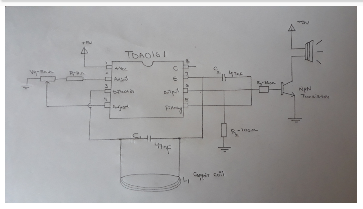
Circuit Diagram:11. Place TD0161 Proximity Detector IC on the bread board
12. connect Pin 7 of the detector IC with 47nF capacitor as shown in the figure.
13. now connect Pin 3 of the IC with 47nF capacitor
14. Connect 1k ohm resistor with Pin 2 of the detector IC
15. Now insert the 5k ohm potentiometer on the bread board with its one terminal connected to the 1k ohm resistor.
16. Connect the one terminal of the potentiometer with Pin 4 of the IC.
17. Now connect 330ohm resistor with the Pin 6 of the detector IC
18. Connect Pin 100ohm resistor with Pin 6 of the IC and other terminal to the ground.
19. Now place a transistor on the bread board through the 330ohm resistor as show in the figure.
20. Connect the NPN transistor emitter terminal to the ground and base to the 330ohm resistor
21. Now connect the 5V buzzer with one of it’s terminal connected to the collector of NPN transistor and other terminal to the power supply.
22. Take the copper coil of winding turns 150-200 and of approximately 6cm diameter as shown in the figure.
23. Connect the positive and negative rails of the bread board as shown in the circuit below.
24. Connect the two ends of copper coil to the Pin 7 and Pin 3 of the Detector IC through a series capacitor as shown in the circuit below.
25. Connect the power supply with its positive terminal to the positive rail of the bread board and negative terminal to the negative rail of the bread board.
26. So when we bring any metal near to the copper winding coil, the IC detector transforms the voltage and regulates through it. Enabling the buzzer to indicate the detection of metal.
27. And when we take our metal away from the copper coil the buzzer stops indicating the metal around it.
So this is the basic working and principle of metal detector, the copper coil winding enables the voltage flow across the IC, and making the buzzer to indicate for the detection.
To buy electronic parts order them from UTSOURCE.net
Thank You


Comments
Please log in or sign up to comment.