This project idea has been floating around my head for a few years now. I had been curious about how an irrigation or sprinkler system operated electronically for some time. Every time something went wrong with our sprinkler system growing up, I would think, "This is wrong, why is this the way these systems are?" haha... I am sure many of you who have ever lived somewhere with a sprinkler system have had similar experiences. More recently, our current system has 5 zones, and we want to add 2 additional zones, however, the system does not support 7 zones. I could go on and on in additional issues with the system, but simply it has issues. The controls are strange, it does not work very well, these systems are expensive, and it only goes up if you want more zones.
Little background about common electro-mechanical sprinkler systems. If you did not know, for most of us that live in a city, water comes from the meter. From the meter it goes to a sprinkler valve, and a valve is an electronic solenoid that opens and closes a physical passage through a pipe. So, a sprinkler valve turns the water on and off, as the solenoid is energized electrically. There is a master valve that comes directly from the meter, then there are additional valves that go to designated zones throughout a yard. There are various practices for laying out zones, which we will not go into here, however, ultimately it depends on the pressure of your water from the city how far it can be spread out. From these zoned valves water goes through pvc pipes to your sprinklers. In summary, water goes meter to master valve to zone valve to pipe to sprinkler.
So, time to do some reverse engineering. Of course, I first checked craigslist, and found the same model sprinkler controller I have. I went and bought it from this old dude, who wanted to meet at his sons hockey practice haha... Anyway, I took it apart, and ran through all the copper traces until I guessed what was going on. Here's a pic:
There's a lot of analog power stuff, however, the underlying control circuit for the valve was the only thing I found particularly useful, and surprisingly it's pretty simple. It uses a device called a triac to control current flow to the sprinkler valve. A microcontroller pin sends current through a current limiting resistor, a diode, the triac gate, which turns the triac "on," and then current can flow through the triac to energize the sprinkler valve solenoid, which turns a sprinkler zone "on". If you never heard of a triac they are weird little dudes. A triac is helpful for controlling an ac load. Current can be applied both directions, as opposed to most transistors, where a load current flows only from collector to emitter. This is accomplished by basically using two BJT transistors in 1 typical discrete transistor package. I will upload two pictures from wikipedia to illustrate the circuit symbol and equivalent circuit. The two transistors are connected together in two places, and one transistor is PNP and one is NPN. The first transistor is PNP, and the second is NPN. The PNP emitter is connected to the NPN gate, and the PNP gate is connected to the NPN collector. Illustrated here:
I said this was simple in that only handful of components are needed, but admitedly I had never learned about triacs in school and it took me awhile to understand them. This equivalent circuit helps until you think about it too long haha...
The handful of components for this little sprinkler valve control circuit to control 1 sprinkler valve are:
- 1x resistor, 220 ohm, 1/4 watt
- 1x diode, 1n4148
- 1x triac, 2n6071a
- 1x sprinkler valve
- 1x gpio pin
- 1x power supply
The 220 ohm resistor limits current from the microcontroller gpio pin through the 1n4148 small signal diode to the triac gate. A 2n6071a triac is what I found in my sprinkler valve controller, and it is rated for 200V @ 4A load. The sprinkler valves in mine, and most household sprinkler systems is rated for 24V. I did not find definitive information on sprinkler valve current ratings, however, the power supply is only rated for 0.75A.
I went to a local electronics store, and bought the discrete components, resistors, diodes, and triacs, however, two substitutions were required. They were out of 1n4148 diodes so I substituted a 1n4448, and I substituted 2n6071a for a q4006r4. A q4006r4 is basically the same triac, however, it comes in a more convient to220 package and rated at 600V @ 6A. I went to lowes and bought a sprinkler valve to double check the circuit. So, for all practical purposes, that's 3 components per valve. I also acquired a bare protoboard .1" spaced 80x100mm to place the circuit.
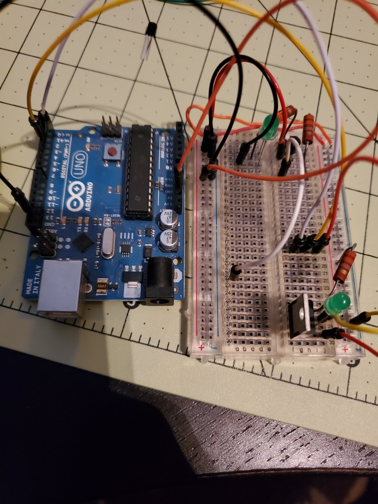
First, I tested a little circuit with the triac and an LED. Here's a pic:
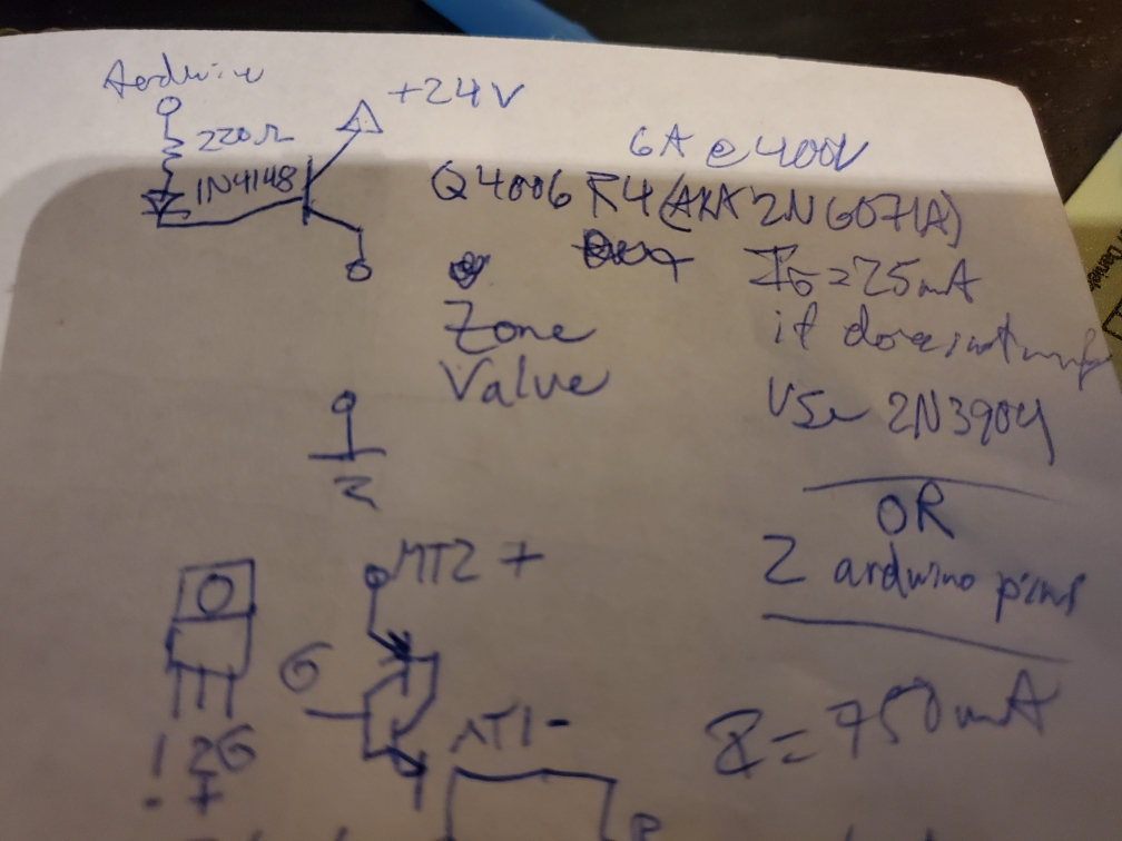
The triac gate needs 25mA and the Uno only outputs 20mA, so I am using 2 gpio here to drive the gate. Here's a drawing of the schematic:
NOTE: When I draw a triac, I just use a BJT symbol.
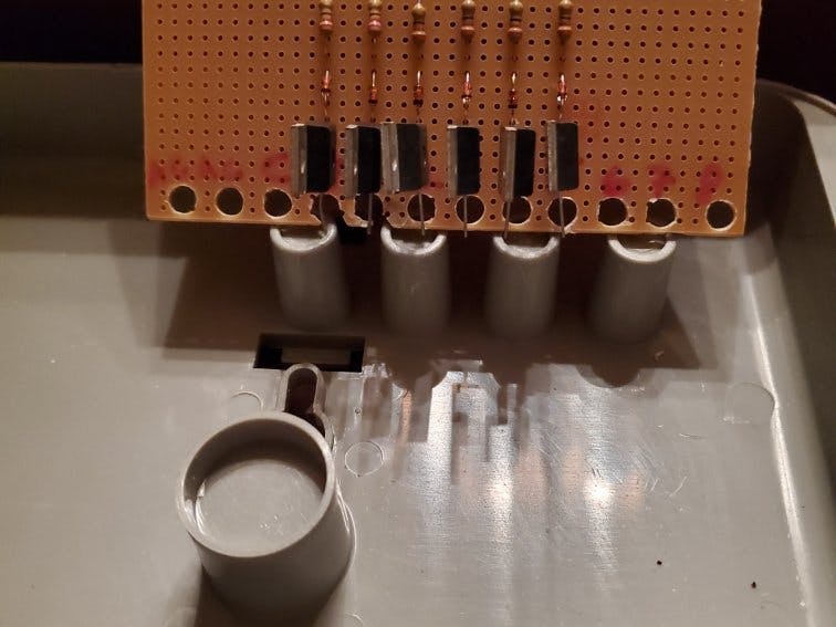
Next, I took the proto board, and drilled holes in it to mount to the old sprinkler controller housing. Here's a pic:
The holes attach screws to the housing, but they also act as screw terminals for the various power connections. Then, I put the parts through the proto board and soldered everything together. Here's a pic:
I bought enough for 6 circuits or 5 zones plus the master valve, however, I drilled holes all the way down the length of the pcb just in case.
I added a 2n3904 to power the gate of the q4006r4 as it needs 25ma, which meant adding current limiting resistor of 1k for the 2n3904 and I needed to change the q4006r4 current limiting resistor to 60 ohm. I couldn't find 60 ohm so I used 2x 30 ohm resistors in series. Here is the finished circuit, and then it mounted in the housing:
I was going to use a tensorflow lite machine learning example I saw posted on the Arduino website. I found a copy of the same program converted to work with the artemis. Code is posted in the code section. I used this program to output to the qwiic oled, yes, no, or unkown, and to turn the sprinklers on when yes is heard.


Comments
Please log in or sign up to comment.