Alright! An Arduino that you built?? Heck yes!
This project is super cool, and will save you some money. A traditional Arduino will cost ya about 30 bucks. Our Arduino will cost us about 10 or 11 bucks, possibly including shipping costs.
If you are wondering -- why would we need to build an Arduino at all? Well, it gives us understanding about how an Arduino works, and also for the thrill. Also because you could be the next one to create the 50 millionth Arduino clone. :)
Before we start: be grateful this only takes a couple hours. Our chip has the Arduino Uno boot loader already preinstalled. If it didn't have it, you'd need to make one yourself! O_O
Okay! Let's begin!!
Materials1. ATmega 328P-PU IC chip (Arduino Uno Boot loader)
2. Geekcreit USB FTDI serial converter adapter
3. Two 22pF Ceramic Capacitors
4. One 100nF Ceramic Capacitor
5. 16 Mhz Crystal
6. Breadboard
7. Jumper Wires
8. 220 Ohm Resistor
9. LED
Now that you've got your parts, lets start!
Step 1: Insert the ChipPut the ATmega 382P-PU in the middle of the breadboard. Make sure that the little dot on the chip is on the bottom left.
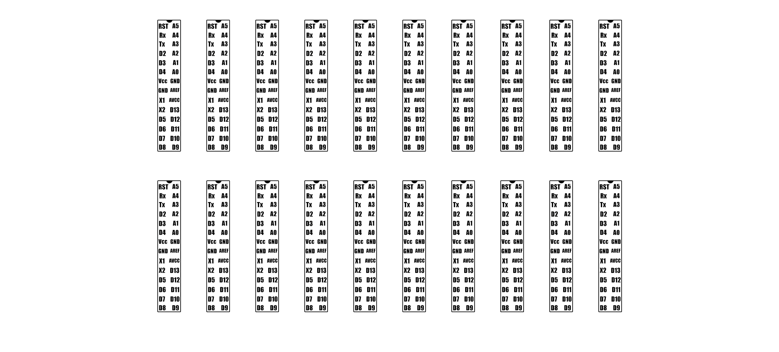
Now, I've added the sticker on top of the chip for visual understanding. It acts as a pin output map without needing to look it up on the Internet.
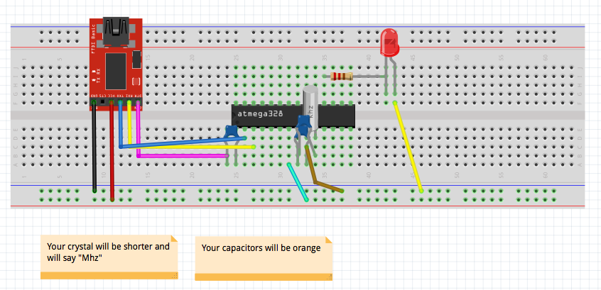
Insert your 16 MHZ crystal under X1 and X2. (Put the crystal just directly underneath the X1 and X2.) Put the crystal in so the numbers on the top are in reading orientation.
Our first 22pF capacitor will go under GND and X1. Put this capacitor to the edge of the main part of the breadboard.
Our second one will go just above our first capacitor and will go into GND and X2.
This step is super short and simple. Connect a jumper wire from VCC on the chip and lead it into our breadboard power, our the plus column on my breadboard.
Place a wire in the GND closest to us, in between the capacitor and the crystal and lead it into our breadboard ground.
If we want to have a light indicator, or use the standard blink program at all, we need to connect our LED. On the opposite side of our IC chip, connect a 220 Ohm resistor into D13. Extend the other leg into any place you want that doesn't connect to the IC chip, the empty space on the right.
The positive leg on will go directly underneath where we put the end of the resistor.
Take a jumper wire, put one leg underneath the other leg of the LED and lead it to breadboard ground.
Step 7: Getting Ready to Upload
Take your 100 nF capacitor. Put one end of the capacitor into RST on the chip.
The first pin on the converter, called DTR, is on the far left. Take a jumper wire and connect it to one end of our 100nF capacitor that is not connected to the IC.
The next pin is called RX. That will go underneath TX on the IC. Yes, it goes to TX, not RX.
The third pin of the converter, TX, will go into RX.
The fourth pin, VCC, will go into breadboard power.
The fifth pin we do not have to use, and the last pin, GND, will go into breadboard ground.
The end of the converter that is a USB end: plug that end into your computer. (This USB type is a little strange, so make sure that you have the right cable)
Open up the Arduino IDE and take the code from this post and put it into the IDE. If you'll notice, it is the LED blink program. Select the correct port on the IDE and set the board type as Arduino/Genuino Uno. Upload the code and it should work!
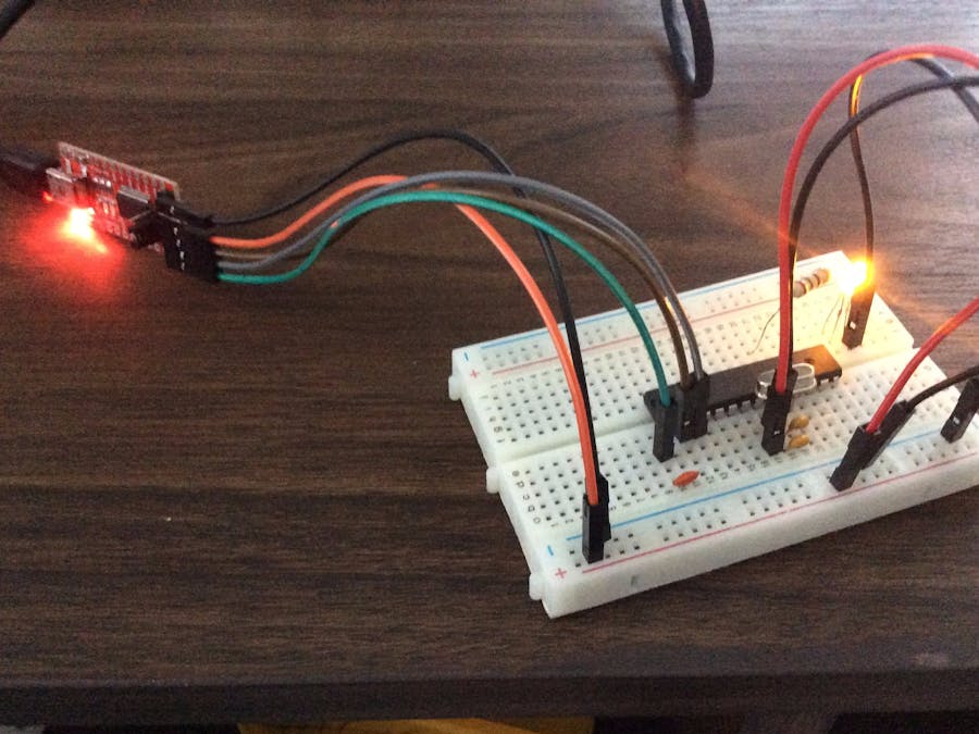
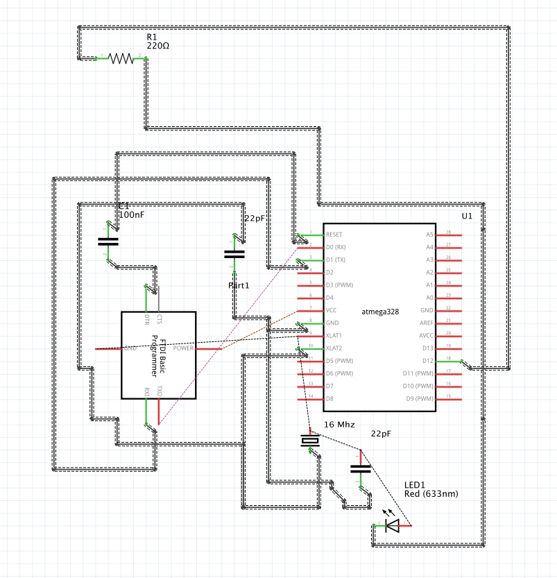
IMPORTANT FOR THE SCHEMATICS!!!! The schematics has a tall and skinny crystal, but this is just on the schematic. Your crystal will go into the same pins but will be a shorter, fatter one. Your capacitors will be orange, and the converter will have male pins, unlike the schematic. (Please excuse me - Fritzing didn't have all the parts I needed to draw the schematic correctly) Check the pictures to know for sure.
Well, that's it folks! Enjoy your home-made Arduino! I officially bestow bragging rights to anyone who replicates this!


_3u05Tpwasz.png?auto=compress%2Cformat&w=40&h=40&fit=fillmax&bg=fff&dpr=2)
Comments
Please log in or sign up to comment.