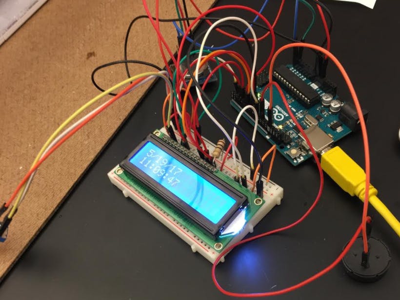
My project is an Arduino alarm clock. I was curious to see if I can make a functional alarm clock with just an Arduino board and an RTC. At first, the numbers only appeared on the serial monitor because I struggled with getting the LCD to light up. I wanted to go step by step in the process so that I can fully understand what was going on. This can be seen here where I prioritized connecting the RTC with the Arduino board to see if I can manipulate the date and time in the code:
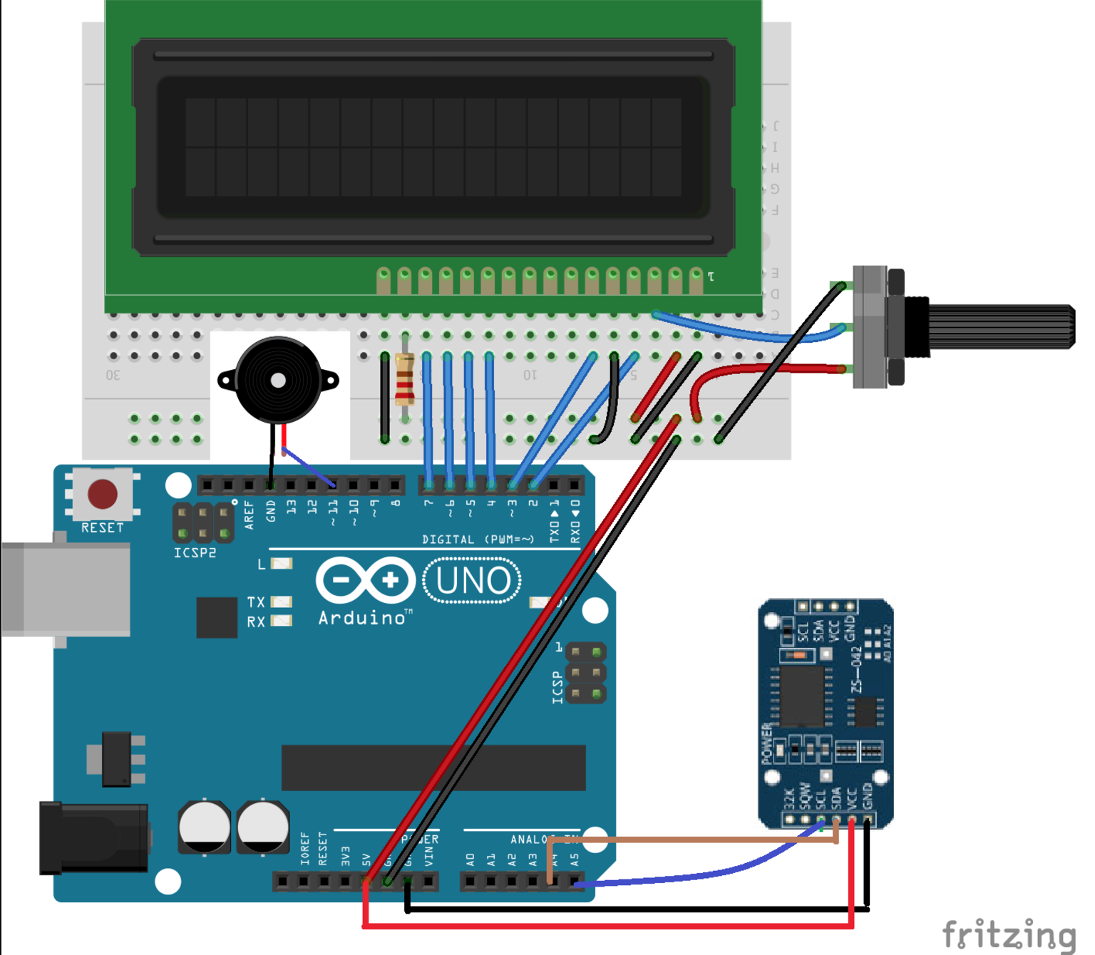
Then, with the help of the circuit model made by Ali Hamza, I was able to get my LCD to light up. I soldered the RTC in the pins GND, SDA, SCL, and VCC. Unfortunately, because she used a different rtc (real time clock), I could not efficiently use her code and library.
A lot of my time was spent trying to find a way to connect both my rtc and LCD. Although I take a computer science class at school, I never really worked with code that's this expansive. Finally, I did find some code that I could use to get both my rtc and LCD together and accurately show the time. It didn't work very well initially and showed a lot of errors in the date/time. I had to change the variables on top (all the #'s) and upload the correct library for it to work. The buzzer came later where I simply added the standard code for a buzzer on the arduino board and changed it so that it would beep at certain time intervals, like a real clock!
And more pictures!
If you follow the steps on Ali Hamza's site on where the wires go, you can then upload the rtc DS1307 in place of the rtc she uses and use the code I modified to suit for the DS1307 and the buzzer. Change the date and time to fit the laptop's date/time and it should be all set!


_ztBMuBhMHo.jpg?auto=compress%2Cformat&w=48&h=48&fit=fill&bg=ffffff)


Comments
Please log in or sign up to comment.