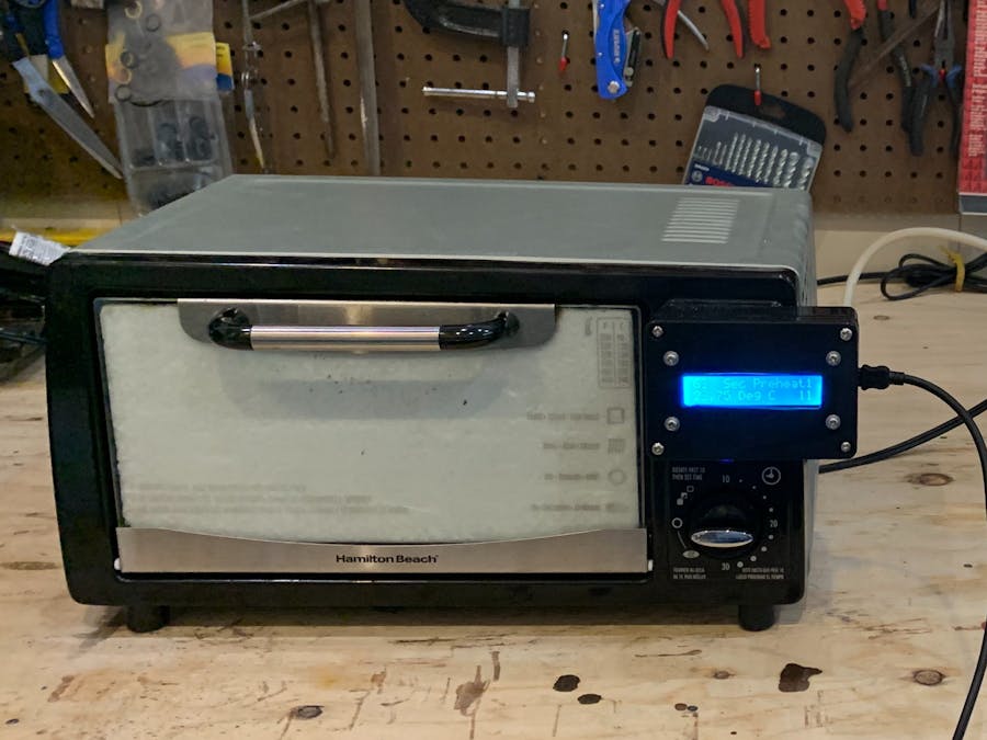
I’m getting too old to solder surface mount devices by hand so I decided to convert a toaster oven into a reflow oven. There are tons of examples on the internet but I believe the best one is from Whizzo. I used many of the Whizoo methods for sealing and insulating the oven but I’m on a tight budget and can’t afford their kit. Besides, it’s a lot more fun to figure out my own design and learn along the way. My requirements are not as challenging as Whizoo’s because I only solder one small board at a time and I use standard tin-lead solder. With the lower melting temperature of leaded solder, I don't need to add a 3rd heating element. An inexpensive Arduino Nano has just enough I/O’s to control two solid state relays (SSRs), read the temperature, and talk to a 16x2 liquid crystal display (LCD). There is no power switch, touchscreen, or input buttons of any kind. If a different solder profile is needed, new Arduino code must be downloaded. The software tells me when to manually open the door during cool-down so there is no servo motor. The oven is powered from a plug strip with a switch. 5 volts DC is provided via a USB cable from a PC or power supply. The minimal features of my oven bring the cost down to under $100.
This is the Hamilton Beach model 311-34 toaster oven I bought for $10 at my local Goodwill store. When looking for a toaster oven to convert, it's best to keep it small and simple.
The Wizoo build guide details how to modify the oven to make it more efficient. There are multiple items that can be modified but I wanted to save money and only do the "heavy hitters". The curves below show the improvement in temperature rise time after each modification. The curve labeled “original” on the far right has a slow temperature rate. Applying RTV sealant to the gaps and holes made the temperature rise quicker plus this is an easy and inexpensive modification. Adding door and bulge insulation showed good improvement and they are also fairly easy to implement. Adding the ceramic blanket was the final item and it increased the temperature rate so well that I stopped making any other modifications.
I chose not to spend any more money to add a 3rd heating element, Reflect-A-Gold tape, door gaskets, or a servo motor. The oven is performing well enough for tin-lead solder. Perhaps I’ll add some of these items in the future if I want to use lead-free solder.
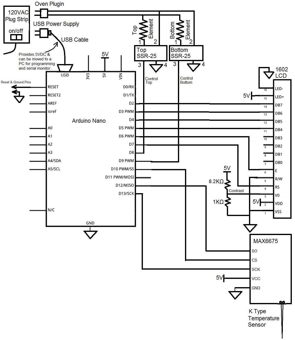
Refer to the schematic at the bottom of this guide to see how the oven was wired. The oven AC plug goes to a plug strip with an on/off switch. A USB power supply is also plugged into the strip to provide 5 volts DC for the Arduino Nano, LCD, and temperature sensor if the cable is not plugged into a PC. A PC is needed to reprogram the Nano or to capture the temperature data for graphing. The top and bottom oven heating elements are controlled by the Nano with separate SSRs. The 1602 LCD is configured in 4 bit mode to reduce the Nano’s I/O count. Fixed resistors are used to set the LCD contrast voltage but a potentiometer could also be used. The MAX6675 digitizes the temperature from a type-K thermocouple and outputs the data over a 3 wire SPI bus to the Nano.
I initially used the threaded M6 thermocouple (shown below) that came with the Max6675 module but I found the temperature reading would lag behind the actual temperature due to the thermal mass of the bolt. This caused the actual temperature to be considerably higher than the measured value.
I melted a test board due to this thermocouple and because I used the upper heating element at full strength. Luckily I didn’t populate the board with components.
I switched to a low mass thermocouple as recommended by Wizoo and it worked much better. The tiny ball that welds the two wires together is able to quickly change temperature. I also limited the time that the top element is turned on to avoid scorching the components. The same test board flowed just fine with the new temperature sensor and software.
The toaster oven came with a wire rack that I don’t use. It also has a "pizza bulge" in the back and a trap door on the bottom that looses a lot of heat.
The high temperature insulated blue wire goes to the other side and is tied to both elements.
Lugs were crimped to the high voltage wires so they could be connected to the SSRs. The original wires had enough length so no additional wires were needed.
The Arduino Nano, 1602 LCD, and Max6675 module were connected using a breadboard and wired to the SSRs.
High Temperature RTV red sealant was applied to all holes and gaps in the oven wall.
The worst air gaps were in the hinged floor.
The front glass of the oven felt like it had a lot of heat loss so I decided to use metal faced insulation called Floor and Tunnel Shield on the door. I chose not to cut an opening to look thru during operation but I may add one in the future.
The insulation makes a pretty good seal around the edges of the door so I didn’t add a high temperature gasket.
There was just enough insulation left over to cover the pizza bulge in the back. This reduces the total area of the oven so the elements can heat up faster. The picture below shows the metal rod (cut from the oven rack) that is used to support the thermocouple. It’s not really necessary now that I use a low mass thermocouple. There are two extra insulation squares on the back wall to make sure there is a gap for airflow when the aluminum tray is installed.
The 8” x 10-5/8” aluminum tray from eBay needed to be cut to 9-5/8” so I drilled 4 holes to hold the plate on my workbench while I used a jigsaw to trim the sides. At 1/32” thick, the plate would bow if not for the 90° flange on the front that adds strength.
A metal tie plate from Home Depot was bent with a shop vise and drilled for mounting the SSR’s to the floor in the control chamber.
Ceramic fiber insulation was cut to fit the sides and top of the oven. This insulation keeps the control chamber from getting hot so the SSR’s don’t need a heat sink or fan. I wore a dust mask, safety glasses and gloves during the installation.
The top half of a plastic project box was cut with a jig saw for the LCD.
The bottom half of the box was attached where the oven control knob was located using the original 4 screws threaded directly into the plastic. The large hole from the original control knob provides access for the wires.
A perf board was used to mount the Nano and Max6675 in the box. Header pins were used to provide easy connection to the board for the LCD and SSR controls. A hole in the side of the box provides access to the Nano’s USB port.
The low mass thermocouple had two flat pins for installation in a meter so I took the plug apart and cut off most of the metal from both pins, leaving just enough to slide under the screw terminals of the Max6675 module.
The LCD is programmed to show the elapsed seconds, profile stage, temperature, and the top and bottom relay PWM control levels (3 and 6 in the picture below).
When it’s time to open the door and cool down, “OpenDoor” is shown. The downward slope is displayed so I can open the door more or less in order to get the desired -2° C per second.
When the reflow cycle is complete, the program displays the maximum temperature, reflow time, soak time, and time to peak.
This shows the oven in use, connected to a PC so that the serial monitor in the Arduino IDE can receive the time and temperature from the Nano. The data is comma delineated so it can be loaded into Excel for plotting the temperature versus time. New Arduino code can also be loaded into the Nano with this configuration. A plug strip with an on/off switch is used to power the oven.
If the PC interface is not needed, 5 volts DC is provided from a USB power supply plugged into the plug strip. I used a TM902C temperature meter to check the accuracy of my circuit so I didn’t melt any more boards.
My Arduino Code is very rudimentary with lots of room for improvements. Someday I may learn how to use the Arduino PID functions, interrupts, timers, and all the other fancy stuff but for now, I’ll just enjoy having a reflow oven. The Nano reads the oven temperature from the Max6675 over a SPI bus using the code from this stackexchange post. The Nano then displays the time and temperature on the 1602 LCD using the liquidcrystal.h Arduino library. The main loop repeats every second and uses a "switch case" statement to adjust the heating based on the temperature. The two heater SSRs are independently controlled and can have 7 different drive strengths. The “On Time” and “Off Time” pulse width are defined in the table below:
This scope picture shows an SSR control signal set to heating level 1.
Once the oven modifications were completed, a dozen test runs were performed to adjust the PWM settings and temperature trip points.
I use Kester, no clean SnPb solder paste purchased as part number 247-SnPb-15 from Amazon for $10.99 in a 15 gram syringe. The Kester reflow profile is given below.
No ramp down rate is given but other sites say it should be less than 5 deg/Sec and 2 deg/Sec is optimal. This rate is adjusted manually by the operator.
The profile shown below was produced after the modifications and test runs were completed. All parameters from the Kester profile are satisfied. The stage names and PWM values shown on the LCD are given on the curve. 8 seconds after reaching 212° C, the code displays “OpenDoor”. At this time, the temperature has risen to 220° C but as soon as the door is cracked open, it starts to fall. The door opening is adjusted manually based on the down-slope value on the LCD. The door is completely opened by the time the temperature reaches 130° C.
The solder paste shown below was applied to each pad using a syringe tip, (I didn't have a stencil).
Unfortunately I used too much solder paste on my first board causing several shorts and parts to move. After some manual work with a soldering iron, flux, and wick, the board was eventually fixed but I learned a valuable lesson.
The lesson is, for complex boards buy a stencil like the one shown below. It applies the perfect amount of solder paste to each pad. For less complex boards, I try to use a minimal amount of paste and remove excess with a toothpick.
The next board ended up needing no solder cleanup, thanks to the stencil.
I'll update this project if I make any changes to my oven.
Let me know if you have any questions.


Comments
Please log in or sign up to comment.