


Hardware components | ||||||
| × | 1 | ||||
| × | 1 | ||||
| × | 1 | ||||
 |
| × | 3 | |||
 |
| × | 1 | |||
| × | 1 | ||||
| × | 1 | ||||
| × | 1 | ||||
Software apps and online services | ||||||
 |
| |||||
Hand tools and fabrication machines | ||||||
 |
| |||||
This article is about an RPOf circuit for the Raspberry Pi using a Trinket, thus a tRPOf. The main difference from previous ones, is that this project uses a standard Adafruit Trinket as microcontroller instead of the MSP430 in order to use "off the shelf" components with less effort of programming. Compared with the first RPoF circuit based on the MSP430, this one uses only two main off the shelf blocks and a minimal external components: the Trinket and the LiPo charger that acts also as relay. Because the use of the battery, the circuit acts also as a UPS and using the right battery can power a Raspberry for few hours as well without the need to have an external power supply.
Block SchematicThe Trinket controls the output of the DC/DC converter (enable pin). The converter acts also as battery charging when a power supply is applied.
Project SpecificationsThe tRPOf will performs these activities:
- Turn ON the Raspberry when the push button is pressed and the Raspberry is Off
- Turn OFF safely the Raspberry when the push button is pressed and the Raspberry is On
Let's see the operation in more detail.
The key to control the Raspberry power is the converter. It has an enable signal that control the 5V output. The Trinket is powered directly from the battery, not the converter, so is always powered in order to control the operations. The LED indicates the status:
- Off -> Raspberry powered off
- On -> Raspberry powered on
- Flashing slow -> Raspberry powering up
- Flashing fast -> Raspberry shutting down
The GPIO4 and GPIO6 are used to exchange information with the Raspberry.GPIO4 (output from Trinket) is used to inform the Raspberry to start the shutdown sequence. The GPIO6 is used by the Trinket to monitor the Raspberry status. If high the Raspberry is running; if low the Raspberry is shutted down and thus the power supply can be removed.
Shopping ListFor the project, we'll use :
Applying/Removing PowerThe PowerBoost can remove the output depending the enable signal applied to it. So the converter acts also as relay to apply or remove power to the Raspberry Pi. By default the enable signal on the PowerBoost is pulled up to the PowerBoost power. Note: When the PowerBoost is connected to a USB charger, the enable signal is pulled up toward 5V! When powered only from the battery, the signal pull up is around 3V. This means that to correctly control the power an external transistor is needed if the microcontroller has 3V signals.
Trinket ConnectionsAll the five available I/O will be used. All of them will be set as I/O :
- PB0 - input - pushbutton
- PB1 - output - LED pushbutton
- PB2 - output - to PowerBoost enable
- PB3 - output - to GPIO4 (shutdown command)
- PB4 - input - to GPIO6 (shutdown feedback)
The pushbutton is connected to a pull up and to the ground.When pushed the input go low. The function for debounce also invert the reading. Basically when the signal goes high exit immediately signaling low goes low waits few minutes, then check again and if still low, waits for the signal to go back high again and then return notifying high.
The LED is connected to the ground and to the output, so forcing the output high set the LED on.
The shutdown command is active low, so normally is high and goes down when the Raspberry has to shutdown.
The shutdown feedback is low when the Raspberry is shut down and high when the Raspberry is running.
The PowerBoost enable signal, on the PowerBoost, is pulled up from the PowerBoost main power. This is normally 3V when only the battery is connected. When the USB is also connected for charge, it's 5V. Because of that is necessary to use a transistor to control the enable on the booster and thus the logic is negated.
The PowerBoost enable is normally high (high to the transistor base, means grounding the enable pin on the PowerBoost) and goes low when the 5V need to be applied to the Raspberry.
SoftwareThe software running in the Trinket is very trivial. Basically there are two state machines, one to handle the main flow and one to handle the LED blinking.
There are 5 states :
- STEADY_OFF
- WAIT_ON
- STEADY_ON
- WAIT_OFF
- LAST_DELAY
After the bootstrap, the state machine is in the state STEADY_OFF. When pressing the pushbutton, the power is enabled, the LED is set to flash slow and the shutdown command is in running mode (high) then the state is changed in WAIT_ON.
In this state nothing happens until the reading of the shutdown feedback indicate the Raspberry is running. When this happens the state is changed in STEADY_ON setting the LED On (not flashing).
In this state a press of the pushbutton cause the shutdown command to go low and the LED is set to flash fast, then the state is changed in WAIT_OFF.
When the shutdown feedback goes low indicating the Raspberry completed the shutdown, the last state, LAST_DELAY, is engaged to give 7 more seconds of wait time before the power is removed (for safety), then the LED is forced OFF and the state return to STEADY_OFF.
The pushbutton is read including a debounce algorithm and it "fires" when the pushbutton is released.
The code is available on Bitbucket.
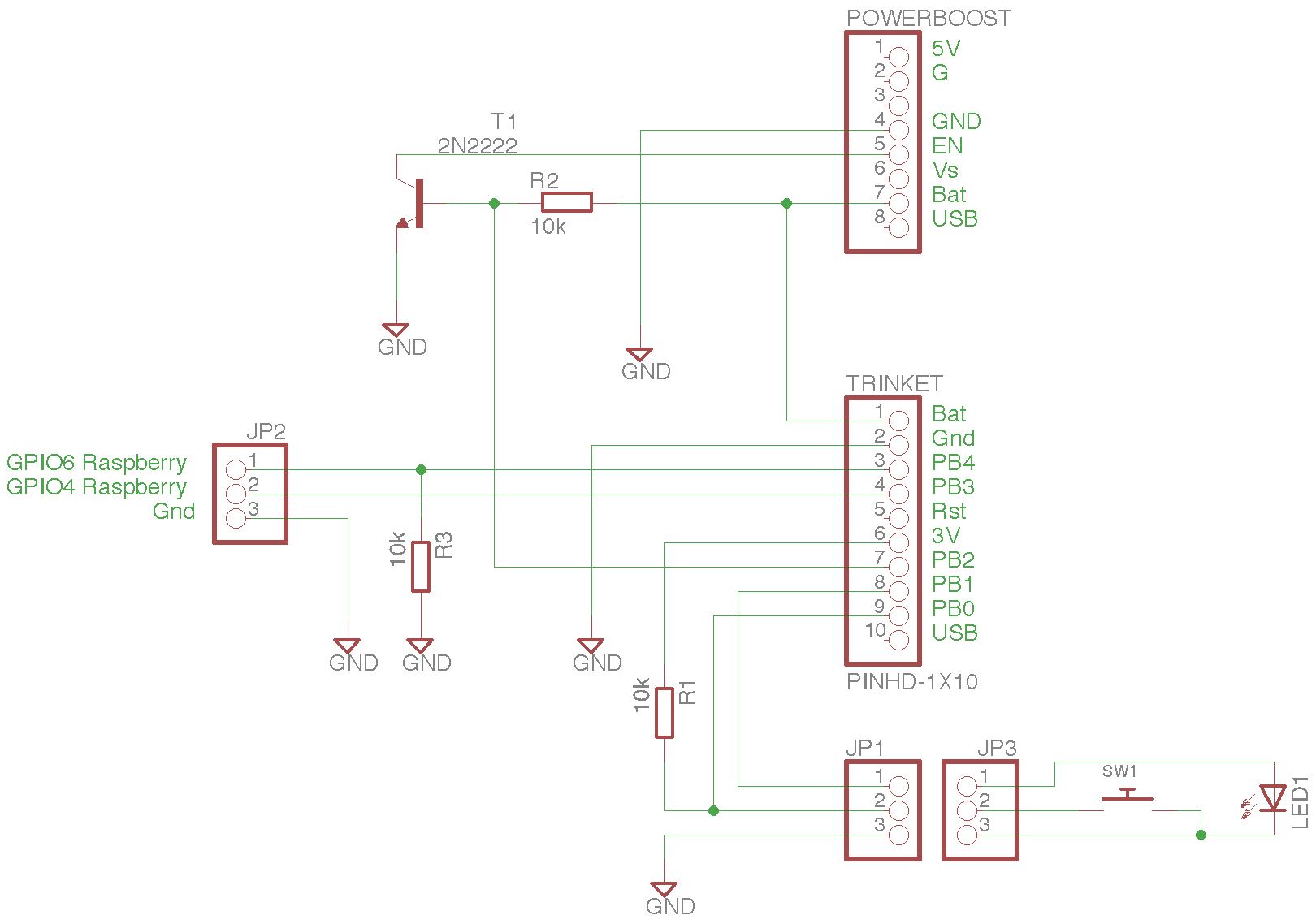
SchematicHere a simple schematic to illustrate how to connect the modules and setting up few pullup/pulldown necessary to the correct working of the system
Raspberry Pi SideOn the Raspberry Pi two I/O pins need to be used. One will check if the line goes low and when this happens, start the shutdown sequence. There is a python code from Adafruit for this purpose used in the NiRis project, so since this project is mainly used for NiRis the GPIO is the one set for the same purpose in NiRis, GPIO4.
The PrototypeThe final assemblyI decided to prepare a PCB to host the Trinket and the converter plus the components needed.
The PCB is public domain (https://easyeda.com/TheFwGuy/rPOf-support-board) and so it can be easily duplicated.

Comments
Please log in or sign up to comment.